Mazda 2: Child-Restraint System Suitability for Various Seat Positions Table
(Europe and countries conforming to the UNECE 16 regulation)
Provided information in the table shows your child-restraint system suitability for various seating position. For installation suitability of other manufacturer child-restraint system, carefully consult the manufacturer's instructions which accompany the child-restraint system.
ISOFIX anchor-secured child-restraint systems
When installing a child-restraint system to the rear seat, refer to the child-restraint system manufacturer's instructions and the Using ISOFIX Anchor on page 2-37 .
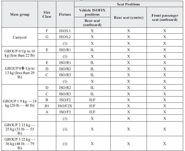
- For the CRS which do not carry the ISO/XX size class identifi cation (A to G), for the applicable mass group, the car manufacturer shall indicate the vehicle specifi c ISOFIX child-restraint system(s) recommended for each position.
Key of letters to be inserted in the above table:
IUF = suitable for ISOFIX forward child-restraints systems of universal category approved for use in this mass group.
IL = suitable for particular ISOFIX child-restraint systems (CRS).
These ISOFIX CRS are those of the “specifi c vehicle”, “restricted” or “semi-universal” categories.
A Mazda genuine child-restraint system can be installed. Regarding child-restraint systems which can be installed, refer to the accessories catalog.
(Except Europe) Regarding child-restraint systems which can be installed to your Mazda, consult an expert repairer, we recommend an Authorised Mazda Repairer.
X = ISOFIX position not suitable for ISOFIX child-restraint systems in this mass group and/or this size class.
i-Size child-restraint systems
Vehicles with the  mark indicated
on the front surface of a rear seatback are i-Size childrestraint
certifi ed.
Marking location
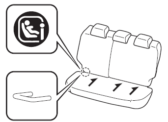
An i-Size child-restraint system can be installed to the specifi ed seat as follows:
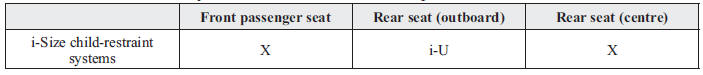
Key of letters to be inserted in the above table: i-U = Suitable for i-Size “universal” child-restraint systems forward and rearward facing.
X = Seating position not suitable for i-Size “universal” child-restraint systems.
NOTE
- An i-Size child-restraint system refers to a child-restraint system which has acquired i-Size category certifi cation for the UNECE 129 regulation.
- Vehicles with the
 mark
mark
indicated on the front surface of a rear seatback are not i-Size child-restraint certifi ed.
Seat belt-secured child-restraint systems
When installing a child-restraint system, the following points must be observed:
- If the child-restraint system does not fi t into the seatback because of
the head restraint,
remove the head restraint so that the child-restraint system fi ts into the
seatback.
Refer to Head Restraints on page 2-11 .
- When installing a child-restraint system to the rear seat, adjust the front seat position so that the front seat does not contact the child-restraint system. Refer to Seat Operation on page 2-5 .
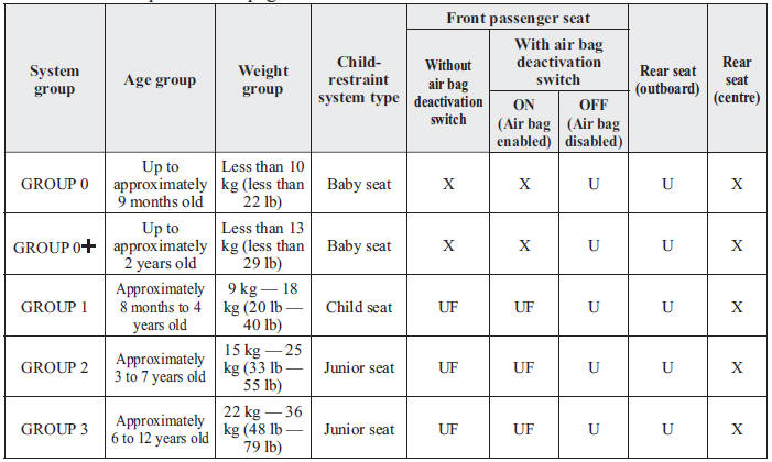
Key of letters to be inserted in the above table: U = Suitable for “universal” category restraints approved for use in this mass group.
UF = Suitable for forward-facing “universal” category restraints approved for use in this mass group.
X = Seat position not suitable for children in this mass group.
(Other countries)
Please comply with the legal regulations concerning the use of child-restraint systems in your country.

