Mazda 2: Control System
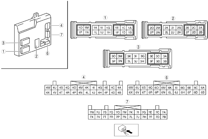
CONTROL SYSTEM LOCATION INDEX
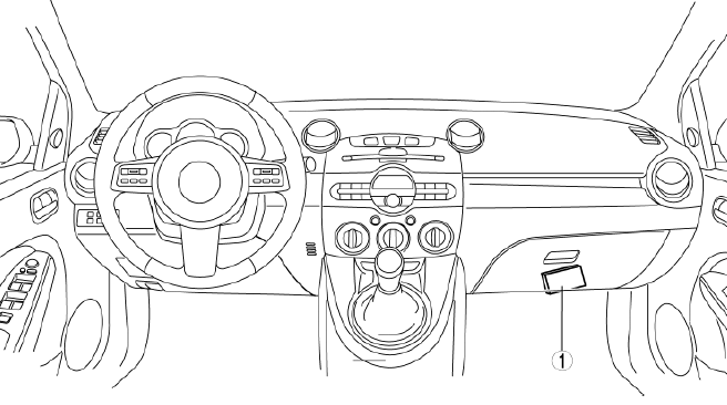
- BCM (body control module)
BODY CONTROL MODULE (BCM) REMOVAL/INSTALLATION
CAUTION:
- When replacing the BCM, the configuration procedure must be performed before removing the BCM. Replacing the BCM without performing the configuration procedure will result in system malfunction.
1. Perform the BCM configuration when replacing it. (See BODY CONTROL MODULE (BCM) CONFIGURATION).
2. Disconnect the negative battery cable.
3. Remove the dashboard under cover. (See DASHBOARD UNDER COVER REMOVAL/INSTALLATION).
4. Remove the glove compartment. (See GLOVE COMPARTMENT REMOVAL/INSTALLATION).
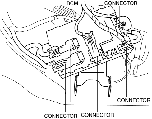
5. Disconnect the connectors at the position shown in the figure.
6. Remove the nuts.
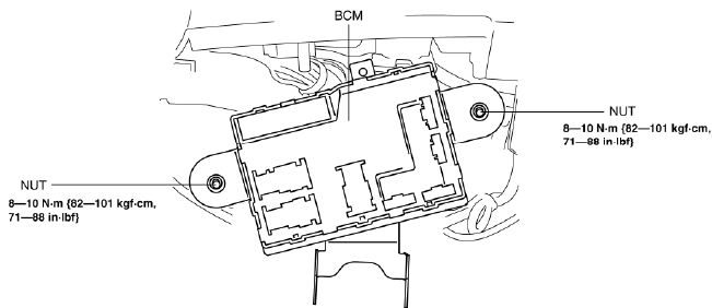
7. Remove the BCM.
8. Install in the reverse order of removal.
BODY CONTROL MODULE (BCM) INSPECTION
1. Remove the dashboard under cover. (See DASHBOARD UNDER COVER REMOVAL/INSTALLATION).
2. Remove the glove compartment. (See GLOVE COMPARTMENT REMOVAL/INSTALLATION).
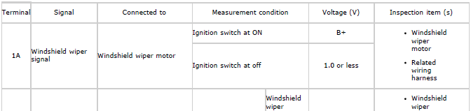
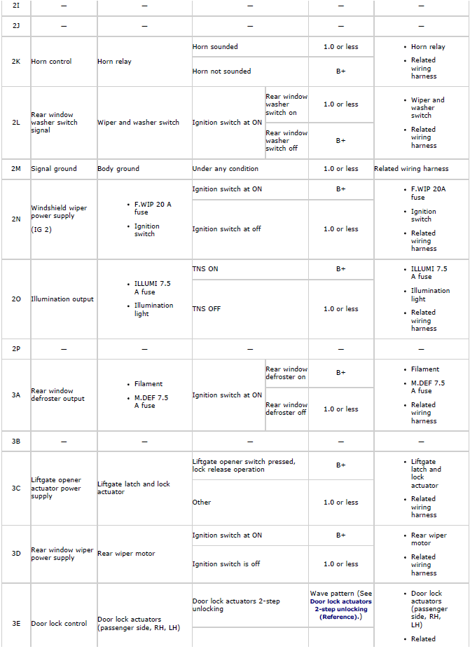
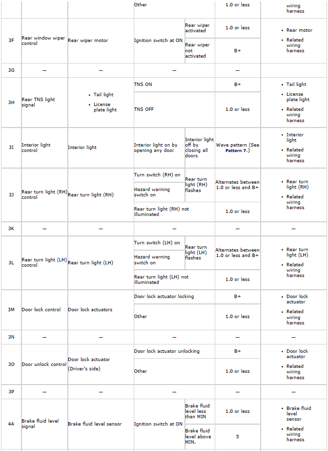
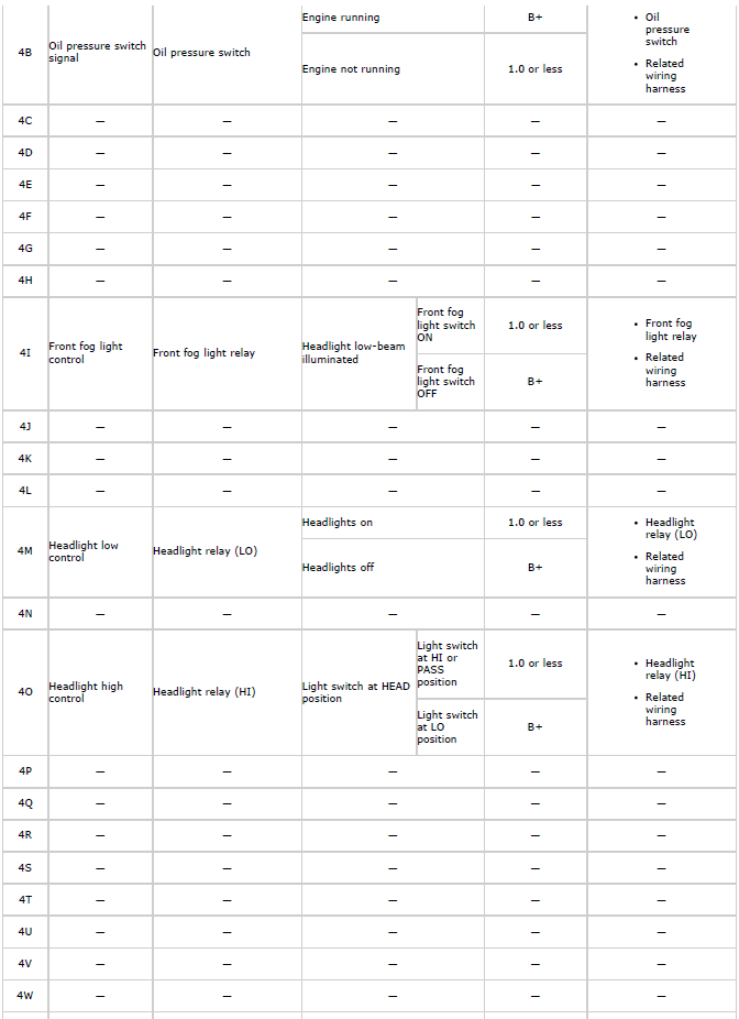
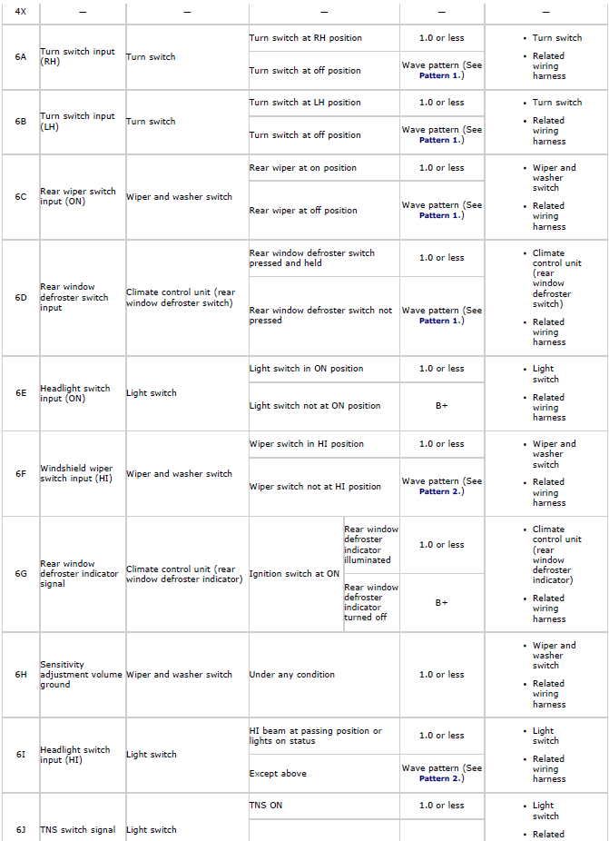
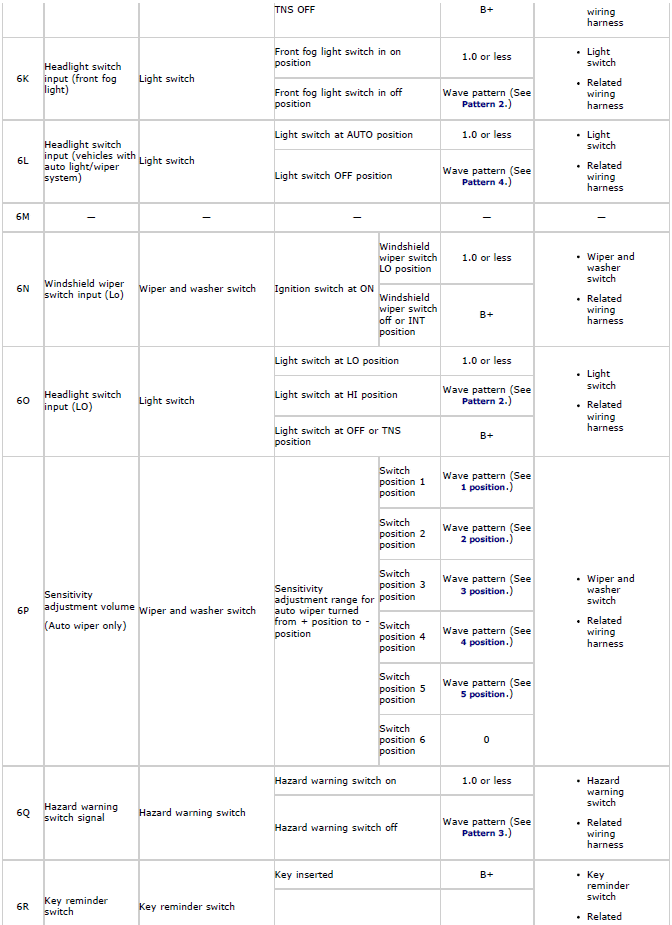
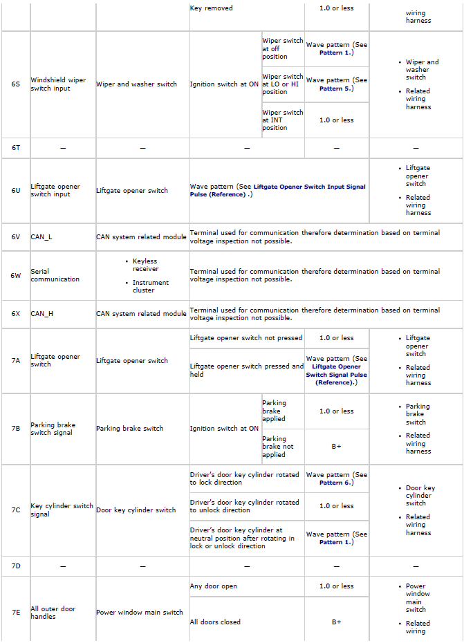
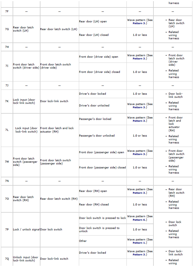
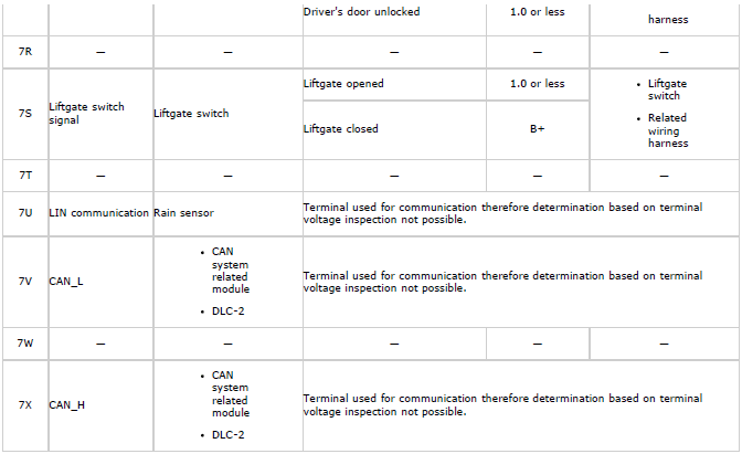
3. Measure the voltage at each terminal and inspect for the continuity between the terminals and ground is as indicated in the Terminal Voltage Tables (Reference).
- If the voltage or continuity is not as specified in the Terminal Voltage
Table (Reference), inspect the parts under
"Inspection item (s)".
- If the system does not work properly even though the parts or related wiring harnesses do not have any malfunction, replace the BCM.
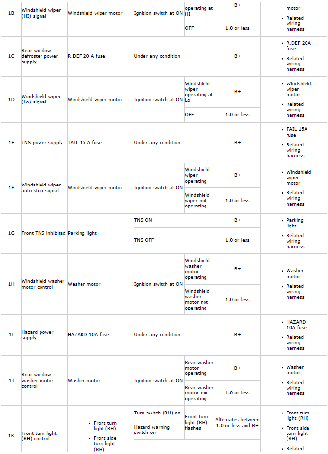
Terminal Voltage Table (Reference)
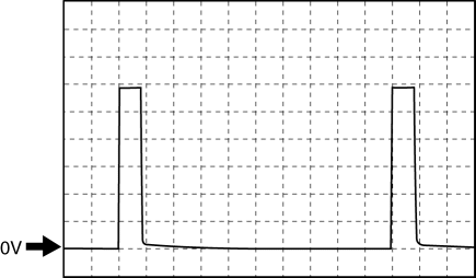
Generated pulse (reference)
Pattern 1
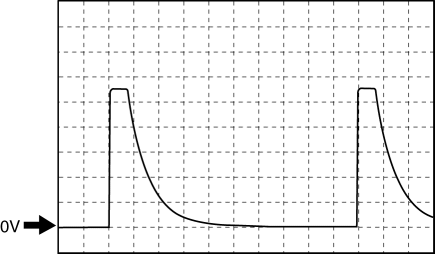
- Terminal:
- Turn switch input (RH): 6A (+) ↔ body ground (-)
- Turn switch input (LH): 6B (+) ↔ body ground (-)
- Rear wiper switch input (ON): 6C (+) ↔ body ground (-)
- Rear window defroster switch input: 6D (+) ↔ body ground (-)
- Windshield wiper switch input: 6S (+) ↔ body ground (-)
- Key cylinder switch signal: 7C (+) ↔ body ground (-)
- Lock / unlock signal: 7P (+) ↔ body ground (-)
- Oscilloscope setting: 2 V/DIV (Y), 1 ms/DIV (X), DC range
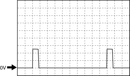
Pattern 2
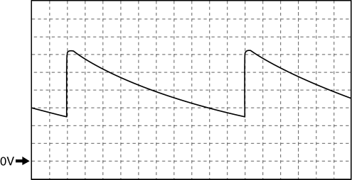
- Terminal:
- Windshield wiper switch input (HI): 6F (+) ↔ body ground (-)
- Headlight switch input (HI): 6I (+) ↔ body ground (-)
- Headlight switch input (front fog light): 6K (+) ↔ body ground (-)
- Headlight switch input (LO): 6O (+) ↔ body ground (-)
- Oscilloscope setting: 2 V/DIV (Y), 1 ms/DIV (X), DC range
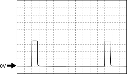
Pattern 3
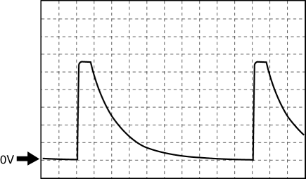
- Terminal:
- Hazard warning switch signal: 6Q (+) ↔ body ground (-)
- Rear door latch switch (LH): 7G (+) ↔ body ground (-)
- Front door latch switch (driver side): 7I (+) ↔ body ground (-)
- Lock input (door lock-link switch): 7K (+) ↔ body ground (-)
- Lock input (door lock-link switch): 7L (+) ↔ body ground (-)
- Front door latch switch (passenger side): 7M (+) ↔ body ground (-)
- Rear door latch switch (RH): 7O (+) ↔ body ground (-)
- Unlock input (door lock-link switch): 7Q (+) ↔ body ground (-)
- Oscilloscope setting: 2 V/DIV (Y), 1 ms/DIV (X), DC range
Pattern 4
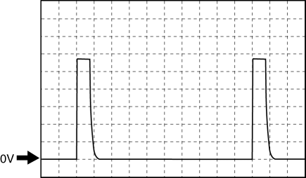
- Terminal:6L (+) ↔ body ground (-)
- Oscilloscope setting: 2 V/DIV (Y), 1 ms/DIV (X), DC range
Pattern 5
- Terminal: 6S (+) ↔ body ground (-)
- Oscilloscope setting: 2 V/DIV (Y), 1 ms/DIV (X), DC range
Pattern 6
- Terminal:
- Key cylinder switch signal: 7C (+) ↔ body ground (-)
- Lock / unlock signal: 7P (+) ↔ body ground (-)
- Oscilloscope setting: 2 V/DIV (Y), 1 ms/DIV (X), DC range
Pattern 7
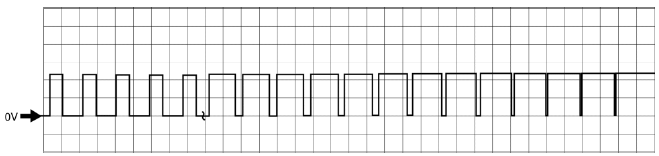
- Terminal: 3I (+) ↔ body ground (-)
- Oscilloscope setting: 5 V/DIV (Y), 5 ms/DIV (X), DC range
Liftgate Opener Switch Input Signal Pulse (Reference)
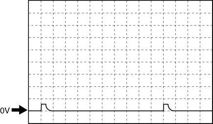
Liftgate opener switch not pressed

- Terminal: 6U (+) ↔ body ground (-)
- Oscilloscope setting: 2 V/DIV (Y), 1 ms/DIV (X), DC range
- Measurement condition: Liftgate opener switch not pressed
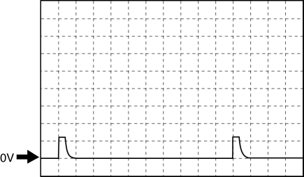
Liftgate opener switch pressed
- Terminal: 6U (+) ↔ body ground (-)
- Oscilloscope setting: 2 V/DIV (Y), 1 ms/DIV (X), DC range
- Measurement condition: Liftgate opener switch pressed
Liftgate Opener Switch Signal Pulse (Reference)

- Terminal: 7A (+) ↔ body ground (-)
- Oscilloscope setting: 2 V/DIV (Y), 1 ms/DIV (X), DC range
- Measurement condition: Liftgate opener switch pressed
Door lock actuators 2-step unlocking (Reference)
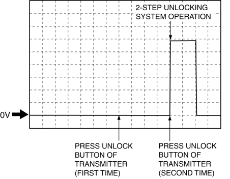
- Terminal: 3E (+) ↔ body ground (-)
- Oscilloscope setting: 2 V/DIV (Y), 2 ms/DIV (X), DC range
- Measurement condition: Door lock actuators 2-step unlocking
Sensitivity adjustment volume (Reference)
1 position
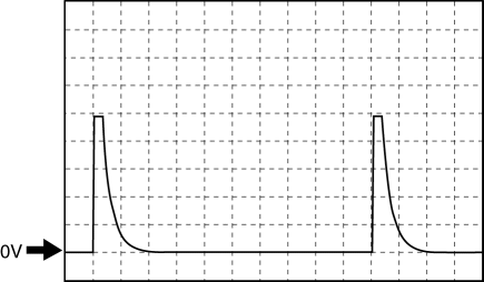
- Terminal: 6P (+) ↔ body ground (-)
- Oscilloscope setting: 2 V/DIV (Y), 1 ms/DIV (X), DC range
2 position
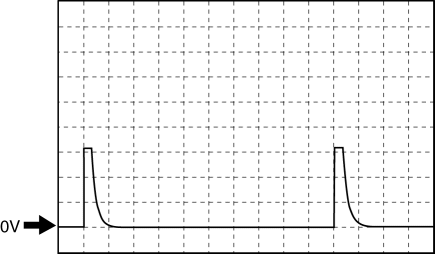
- Terminal: 6P (+) ↔ body ground (-)
- Oscilloscope setting: 2 V/DIV (Y), 1 ms/DIV (X), DC range
3 position
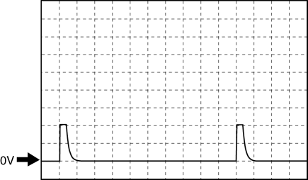
- Terminal: 6P (+) ↔ body ground (-)
- Oscilloscope setting: 2 V/DIV (Y), 1 ms/DIV (X), DC range
4 position
- Terminal: 6P (+) ↔ body ground (-)
- Oscilloscope setting: 2 V/DIV (Y), 1 ms/DIV (X), DC range
5 position
- Terminal: 6P (+) ↔ body ground (-)
- Oscilloscope setting: 2 V/DIV (Y), 1 ms/DIV (X), DC range
BODY CONTROL MODULE (BCM) BRACKET REMOVAL/INSTALLATION
Removal
1. Disconnect the negative battery cable.
2. Remove the dashboard under cover. (See DASHBOARD UNDER COVER REMOVAL/INSTALLATION).
3. Remove the glove compartment. (See GLOVE COMPARTMENT REMOVAL/INSTALLATION).
4. Remove the BCM. (See BODY CONTROL MODULE (BCM) REMOVAL/INSTALLATION).
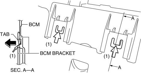
5. Insert a fastener remover in the direction of the arrow (1) shown in the figure and release the tabs.
CAUTION:
- Because the tabs will break if they are bent excessively, bend the tabs only so far as to allow them to release from the BCM.
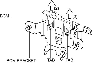
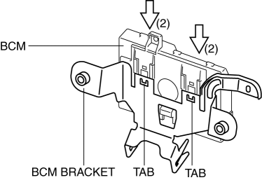
6. Pull the BCM in the direction of the arrow (2) as shown in the figure and remove the BCM bracket.
Installation
1. Bend the tabs in the direction of the arrow (1) so that clearance (a) indicated in the figure is within the specification.
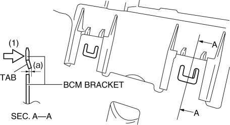
Clearance
- a: 0.8―1.2 mm {0.032―0.047 in}
2. Press the BCM in the direction of the arrow (2) as shown in the figure and install it.
3. Install the BCM. (See BODY CONTROL MODULE (BCM) REMOVAL/INSTALLATION).
4. Install the glove compartment. (See GLOVE COMPARTMENT REMOVAL/INSTALLATION).
5. Install the dashboard under cover. (See DASHBOARD UNDER COVER REMOVAL/INSTALLATION).
6. Connect the negative battery cable.
BODY CONTROL MODULE (BCM) CONFIGURATION
1. Connect the M-MDS (IDS) to the DLC-2.
2. After the vehicle is identified, select the following items from the initial screen of the M-MDS.
- When using the IDS (laptop PC)
- Select "Module Programming".
- Select "Programmable Module Installation".
- Select "BCM/GEM".
3. Perform the configuration according to the directions on the screen.
4. Retrieve DTCs by the M-MDS, then verify that there is no DTC present.
- If a DTC (s) is detected, perform the applicable DTC inspection. (See DTC TABLE [BCM] ).
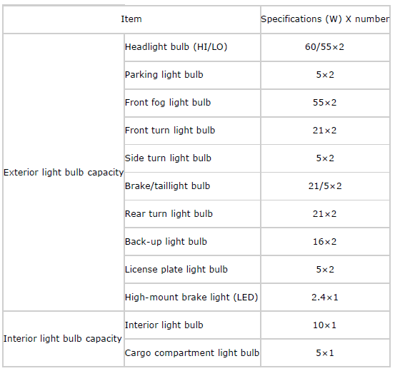
BODY AND ACCESSORIES TECHNICAL DATA