Mazda 2: Dynamic Stability Control System
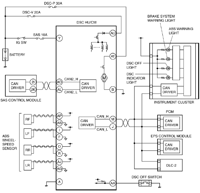
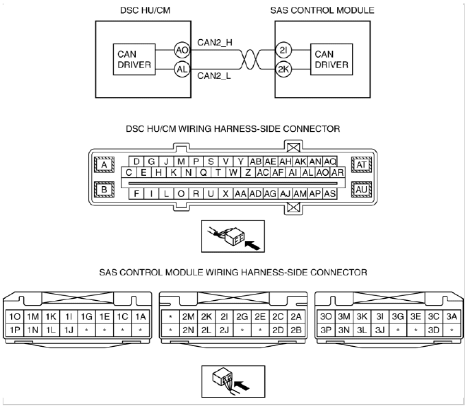
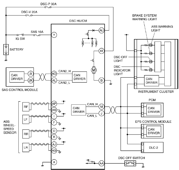
DYNAMIC STABILITY CONTROL SYSTEM WIRING DIAGRAM
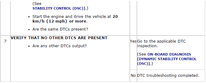
ON-BOARD DIAGNOSIS
On-Board Diagnostic (OBD) Test Description
- The OBD test inspects the integrity and function of the DSC and outputs the results when requested by the specific tests.
- On-board diagnostic test also:
- Provides a quick inspection of the DSC usually performed at the start of each diagnostic procedure.
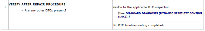
- Provides verification after repairs to ensure that no other faults occurred during service.
- The OBD test is divided into 3 tests:
- Read/clear diagnostic results, PID monitor and record and active command modes.
Read/clear diagnostic results
- This function allows you to read or clear DTCs in the DSC HU/CM memory.
PID/Data monitor and record
- This function allows you to access certain data values, input signals, calculated values, and system status information.
Active command modes
- This function allows you to control devices through the M-MDS.
Reading DTCs Procedure
1. Connect the M-MDS (IDS) to the DLC-2.
2. After the vehicle is identified, select the following items from the initialization screen of the IDS.
- Select "Self Test".
- Select "Modules".
- Select "ABS".
3. Verify the DTC according to the directions on the screen.
- If any DTCs are displayed, perform troubleshooting according to the corresponding DTC inspection.
4. After completion of repairs, clear all DTCs stored in the DSC. (See Clearing DTCs Procedures).
Clearing DTCs Procedures
1. Connect the M-MDS (IDS) to the DLC-2.
2. After the vehicle is identified, select the following items from the initialization screen of the IDS.
- Select "Self Test".
- Select "Modules".
- Select "ABS".
3. Verify the DTC according to the directions on the screen.
4. Press the clear button on the DTC screen to clear the DTC.
5. Switch the ignition to off.
6. Switch the ignition to ON and wait for 5 s or more.
7. Perform DTC inspection. (See Reading DTCs Procedure).
8. Verify that no DTCs are displayed.
PID/Data Monitor and Record Procedure
1. Connect the M-MDS (IDS) to the DLC-2.
2. After the vehicle is identified, select the following items from the initialization screen of the IDS.
- Select "DataLogger".
- Select "Modules".
- Select "ABS".
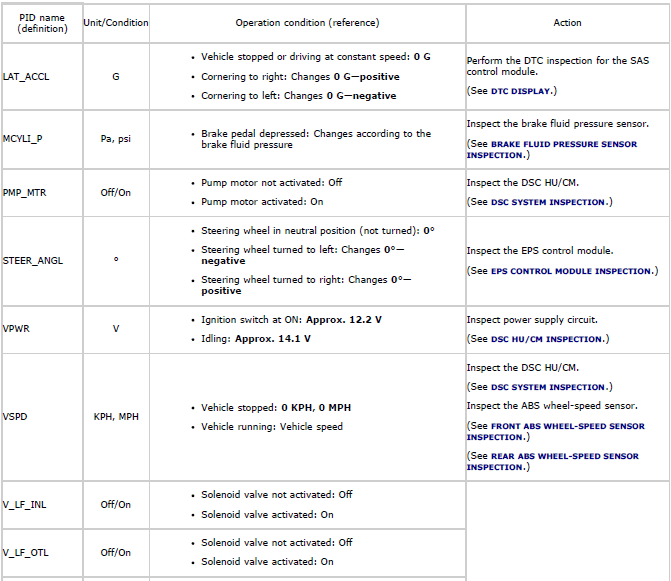
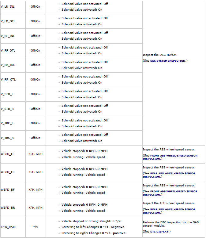
3. Select the applicable PID from the PID table.
4. Verify the PID data according to the directions on the screen.
NOTE:
- The PID data screen function is used for monitoring the calculated value of input/output signals in the module. Therefore, if the monitored value of the output parts is not within the specification, it is necessary to inspect the monitored value of input parts corresponding to the applicable output part control. In addition, because the system does not display an output part malfunction as an abnormality in the monitored value, it is necessary to inspect the output parts individually.
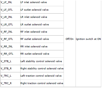
Active Command Modes Procedure
1. Connect the M-MDS (IDS) to the DLC-2.
2. After the vehicle is identified, select the following items from the initialization screen of the IDS.
- Select "DataLogger".
- Select "Modules".
- Select "ABS".
3. Select the simulation items from the PID table.
4. Perform the active command modes function, inspect the operations for each parts.
- If the operation of output parts cannot be verified after the active command mode inspection is performed, this could indicate the possibility of an open or short circuit, sticking, or operation malfunction in the output parts.
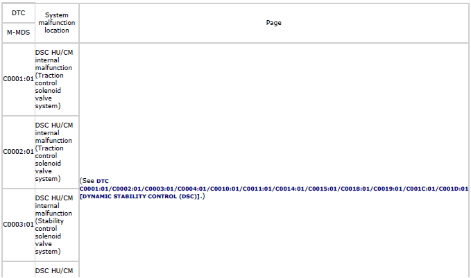
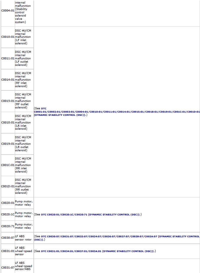
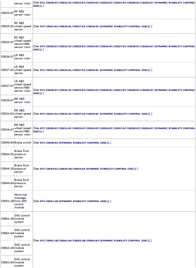
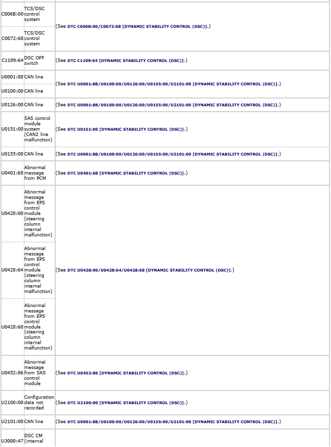
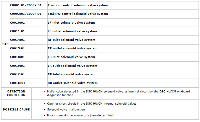
DTC Table
PID/DATA Monitor Table
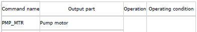
Active Command Modes Table
DTC
C0001:01/C0002:01/C0003:01/C0004:01/C0010:01/C0011:01/C0014:01/
C0015:01/C0018:01/C0019:01/C001C:01/C001D:01
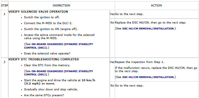
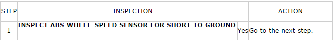
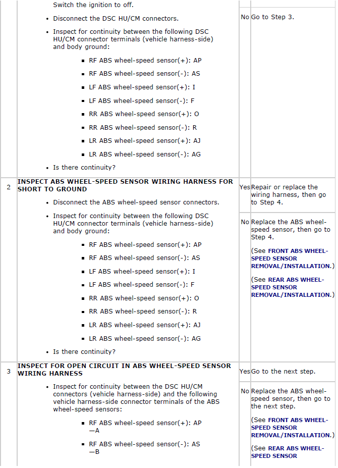
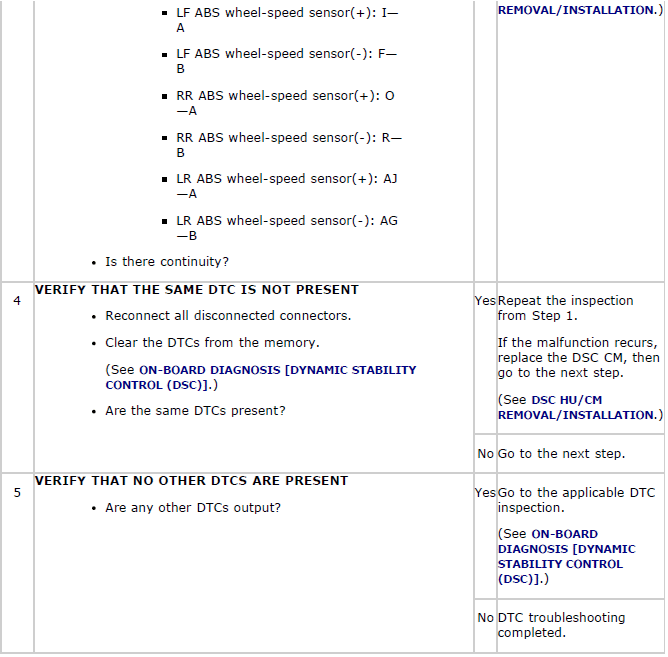
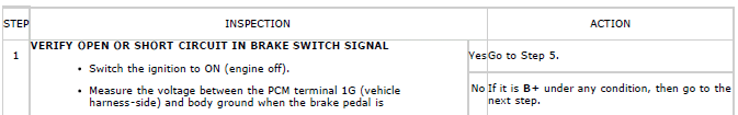
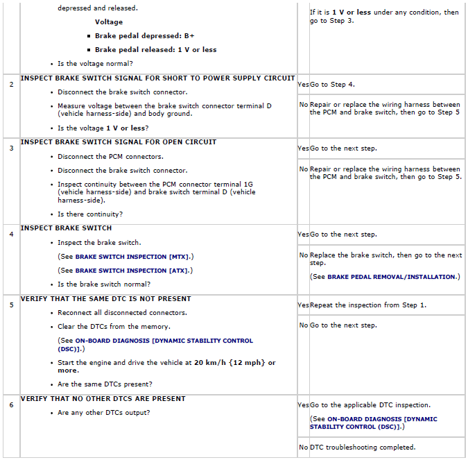
Diagnostic procedure
DTC C0020:01/C0020:1C/C0020:71
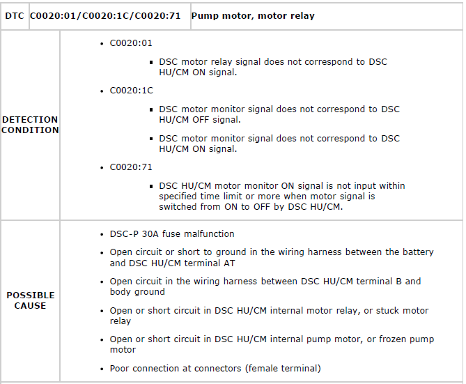
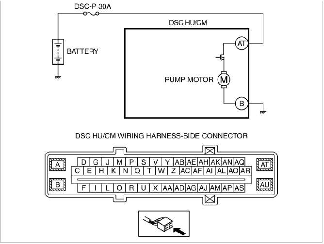
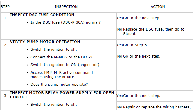
Diagnostic procedure
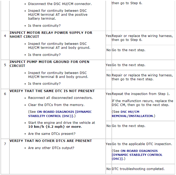
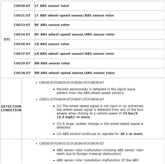
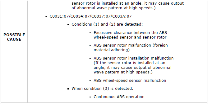
DTC C0030:07/C0031:07/C0033:07/C0034:07/C0036:07/C0037:07/C0039:07/C003A:07
NOTE:
- When only the driving wheels are rotated while the vehicle is jacked up, DTCs C0037:07 and C003A:07 are input to the memory.

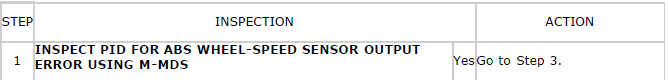
Diagnostic procedure
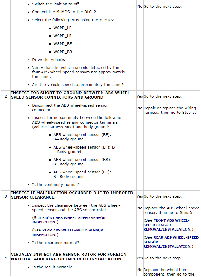
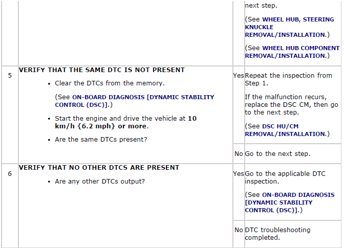
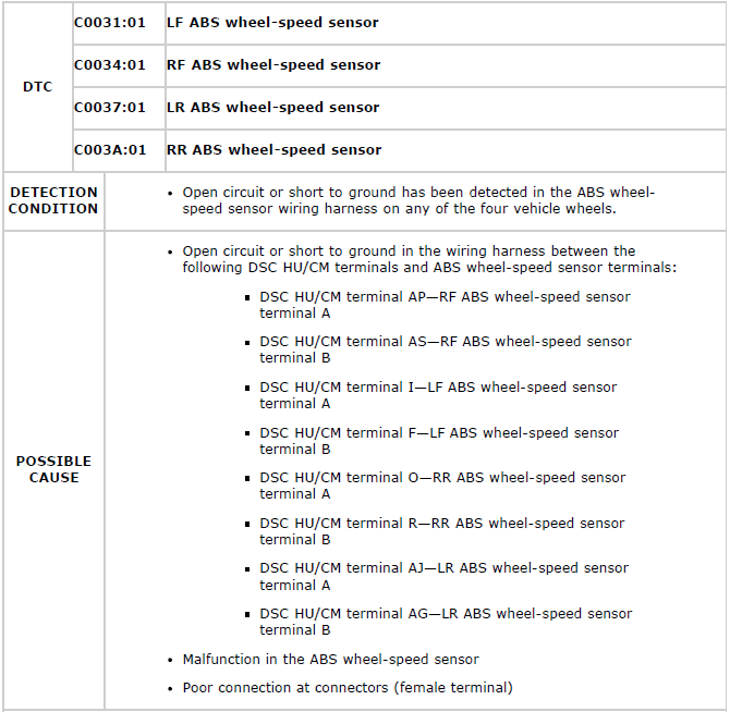
DTC C0031:01/C0034:01/C0037:01/C003A:01
Diagnostic procedure
DTC C0040:64
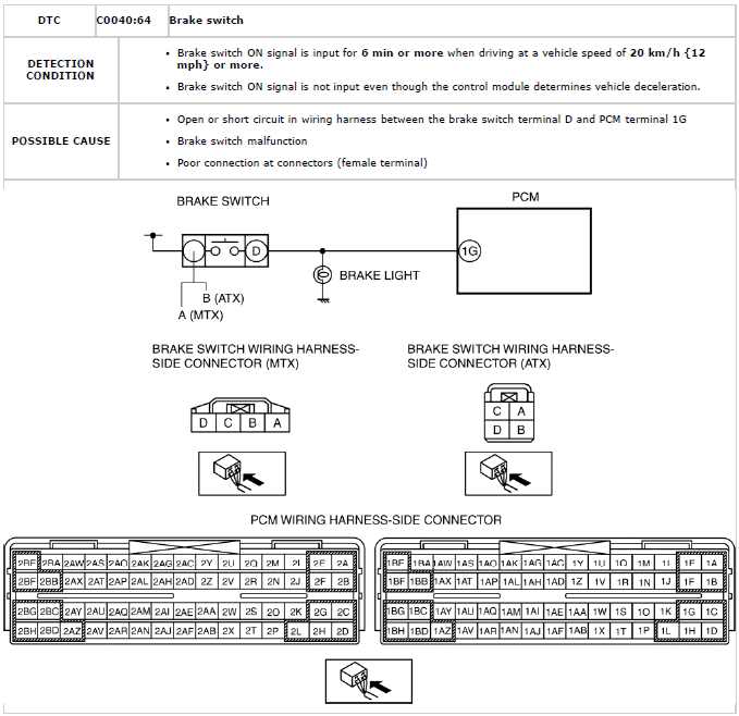
Diagnostic procedure
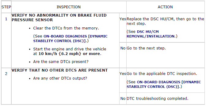
DTC C0044:01/C0044:28/C0044:64
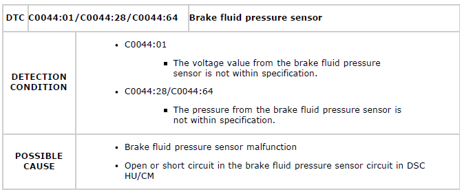
Diagnostic procedure
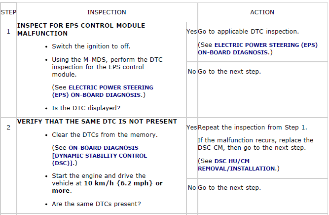
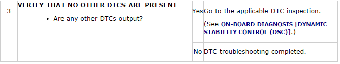
DTC C0051:28
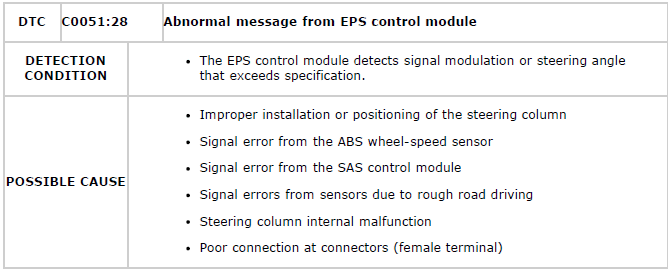
Diagnostic procedure
DTC C0061:28/C0061:64/C0063:28/C0063:64
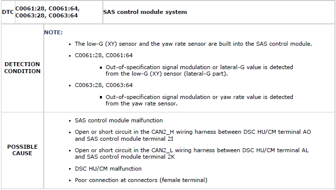
Diagnostic procedure

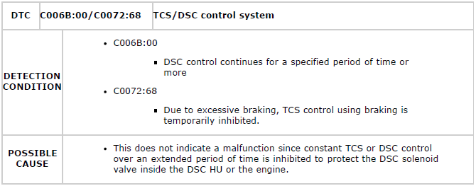
DTC C006B:00/C0072:68
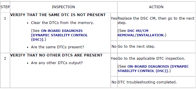
Diagnostic procedure
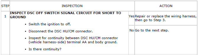
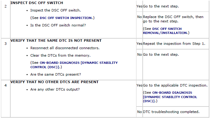
DTC C1109:64
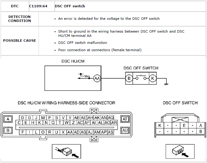
Diagnostic procedure
DTC U0001:88/U0100:00/U0126:00/U0155:00/U2101:00
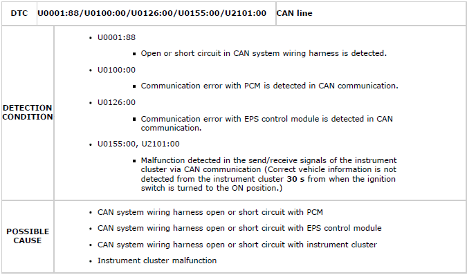
Diagnostic procedure
- Inspect according to diagnostic procedure in BODY & ACCESSORIES. (See FOREWORD [MULTIPLEX COMMUNICATION SYSTEM] ).
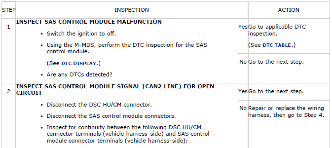
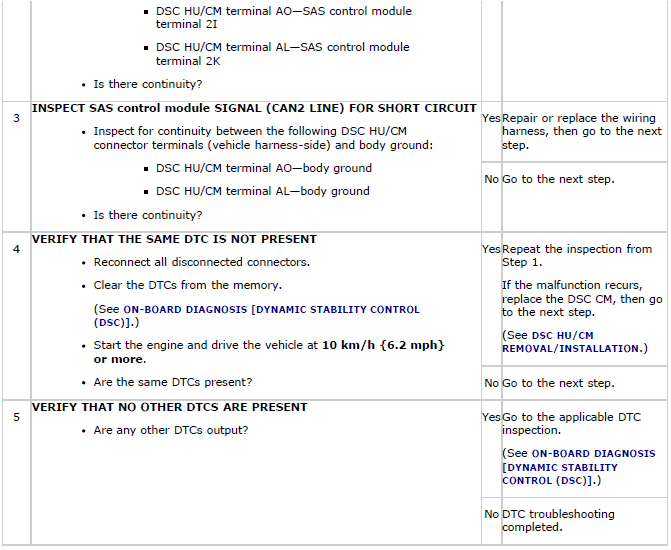
DTC U0151:00
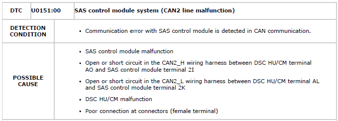
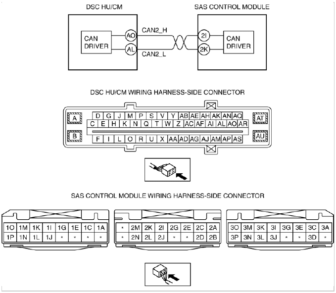
Diagnostic procedure
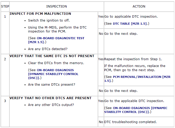
DTC U0401:68
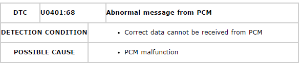
Diagnostic procedure
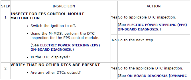
DTC U0428:00/U0428:64/U0428:68
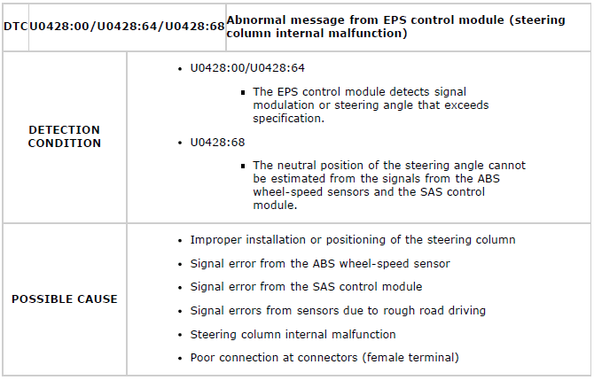
Diagnostic procedure

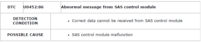
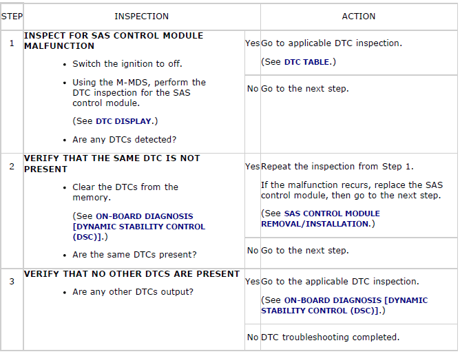
DTC U0452:86
Diagnostic procedure
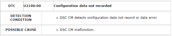
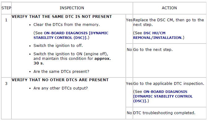
DTC U2100:00
Diagnostic procedure
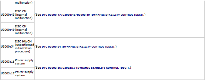
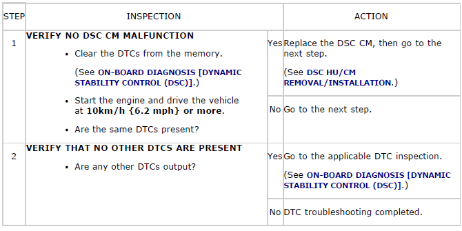
DTC U3000:47/U3000:48/U3000:49
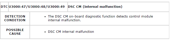
Diagnostic procedure
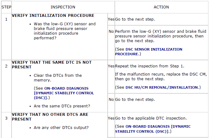
DTC U3000:54
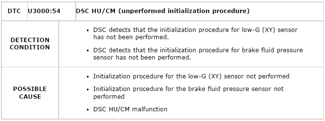
Diagnostic procedure

DTC U3003:16/U3003:17
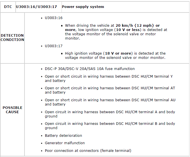
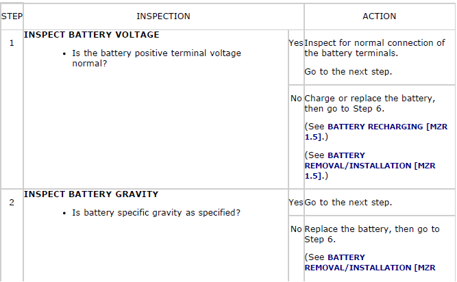
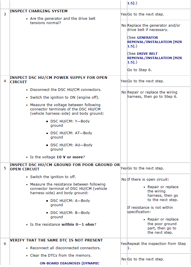
Diagnostic procedure
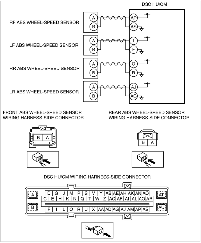
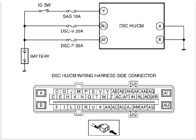
SYSTEM WIRING DIAGRAM
FOREWORD
- Before performing the steps in Symptom Troubleshooting, perform the On-board Diagnostic inspection. To inspect the DTC, follow the DTC Inspection steps. (See ON-BOARD DIAGNOSIS [DYNAMIC STABILITY CONTROL (DSC)] ).

