Mazda 2: Precaution
1. The ABS warning light and/or brake system warning light and/or DSC indicator light illuminate even when the system is normal.
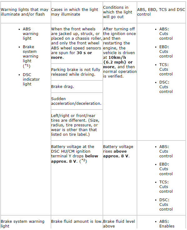
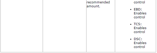
*1 In case where the light may illuminate, only when the DSC HU/CM detects
that a wheel-speed sensor determines that more than the two wheels are
malfunctioning.
*2 If the battery voltage drops below 8 V while the vehicle speed is greater
than
20 km/h {12 mph}, the DSC HU/CM records the DTC U3003:16.
2. Precautions during servicing of the DSC. The DSC is composed of electrical and mechanical parts. It is necessary to categorize malfunctions as being either electrical or hydraulic when performing troubleshooting.
- Malfunction in electrical system
- The control module has an on-board diagnostic function. With this function, the ABS warning light and/or brake system warning light and/or DSC indicator light will illuminate when there is a problem in the electrical system.
Also, past and present malfunctions are recorded in the control module. This function can find malfunctions that do not occur during periodic inspections. Connect the M-MDS to the DLC-2, then switch the ignition to ON. As a result, the stored malfunctions will be displayed on the M-MDS in numeric order by connecting the DLC-2. To find out the causes of the DSC malfunctions, use these on-board diagnostic results.
- If a malfunction occurred in the past but is now normal, the cause is likely a temporary poor connection of the wiring harness.
The control module usually operates normally. Be careful when searching for the cause of malfunction.
- After repair, it is necessary to clear the DTC from the control module memory.
Also, if the DSC related parts have been replaced, verify that the no DTC has been displayed after repairs.
- After repairing the ABS wheel-speed sensor or ABS sensor rotor, or after replacing the control module, the ABS warning light may not go out even when the ignition is switched to ON. In this case, drive the vehicle at a speed of 10 km/h {6.2 mph} or more, make sure the ABS warning light goes out, and then clear the DTC.
- When repairing, if the DSC related connectors are disconnected and the ignition is switched to ON, the control module will mistakenly detect a fault and record it as a malfunction.
- After repairing the SAS control module (yaw rate sensor or lateral acceleration sensor) or the steering angle sensor module (EPS control module), or after replacing the SAS control module, the DSC indicator light may not go out even when the ignition is switched to ON. In this case, drive the vehicle at a speed of 10 km/h {6.2 mph} or more with going straight, make sure the DSC indicator light goes out, and then clear the DTC.
CAUTION:
- In the DSC vehicles, when the DSC HU/CM, SAS control module is replaced, perform the initialization procedure for each sensor. (See DSC SENSOR INITIALIZATION PROCEDURE).
- To protect the control module, make sure the ignition is switched off before connecting or disconnecting the control module connector.
- Malfunctions in hydraulic system
- Symptoms in a hydraulic system malfunction are similar to those in a conventional brake malfunction. However, it is necessary to determine if the malfunction is in a DSC component or the conventional brake system.
- The hydraulic unit contains delicate mechanical parts. If foreign material enters the component, the DSC may fail to operate.
Also, it will likely become extremely difficult to find the location of the malfunction in the event that the brakes operate but the DSC does not. Make sure foreign materials does not enter when servicing the DSC (e.g. brake fluid replacement, pipe removal).
Intermittent Concern Troubleshooting
Vibration method
If malfunction occurs or becomes worse while driving on a rough road or when engine is vibrating, perform the steps below.
NOTE:
- There are several reasons why vehicle or engine vibration could cause an
electrical
malfunction. Some of the things to inspect are:
- Connectors not fully seated.
- Wiring harness not having full play.
- Wires laying across brackets or moving parts.
- Wires routed too close to hot parts.
- An improperly routed, improperly clamped, or loose wiring harness can cause wiring to become pinched between parts.
- The connector joints, points of vibration, and places where wiring harness pass through the firewall, body panels, etc. are the major areas to be inspected.
Inspection method for switch connectors or wiring harnesses
1. Connect the M-MDS to the DLC-2.
2. Switch the ignition to ON (engine off).
NOTE:
- If engine starts and runs, perform the following steps at idle.
3. Access PIDs for the switch you are inspecting. (See ON-BOARD DIAGNOSIS [DYNAMIC STABILITY CONTROL (DSC)] ).
4. Turn switch on manually.
5. Slightly shake each connector or wiring harness vertically and horizontally while monitoring the PID.
- If the PID value is unstable, inspect poor connection.
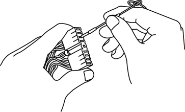
Inspection method for sensor connectors or wiring harnesses
1. Connect the M-MDS to the DLC-2.
2. Switch the ignition to ON (engine off).
NOTE:
- If engine starts and runs, perform the following steps at idle.
3. Access PIDs for the switch you are inspecting. (See ON-BOARD DIAGNOSIS [DYNAMIC STABILITY CONTROL (DSC)] ).
4. Slightly shake each connector or wiring harness vertically and horizontally while monitoring the PID.
- If the PID value is unstable, inspect poor connection.
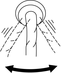
Inspection method for sensors
1. Connect the M-MDS to the DLC-2.
2. Switch the ignition to ON (engine off).
NOTE:
- If engine starts and runs, perform the following steps at idle.
3. Access PIDs for the switch you are inspecting. (See ON-BOARD DIAGNOSIS [DYNAMIC STABILITY CONTROL (DSC)] ).
4. Vibrate the sensor slightly with your finger.
- If the PID value is unstable or malfunction occurs, inspect the sensor for poor connection and/or poor mounting.
Malfunction data monitor method
1. Perform malfunction reappearance test according to malfunction reappearance mode and malfunction data monitor. The malfunction cause is found in the malfunction data.
Connector terminal inspection method
1. Inspect the connection condition of each female terminal.
2. Insert the male terminal to the female terminal and Inspect the female terminal for looseness.