Mazda 2: On-Board Diagnostic System
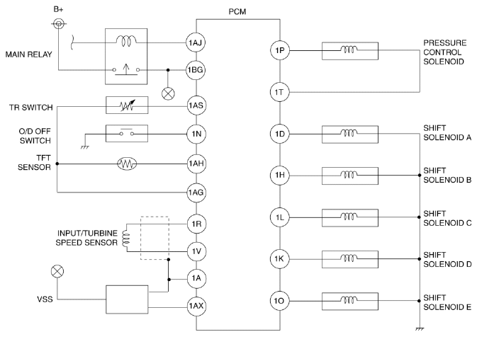
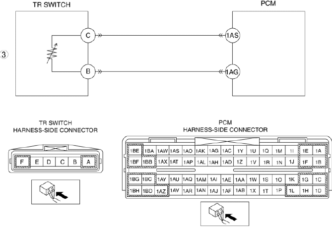
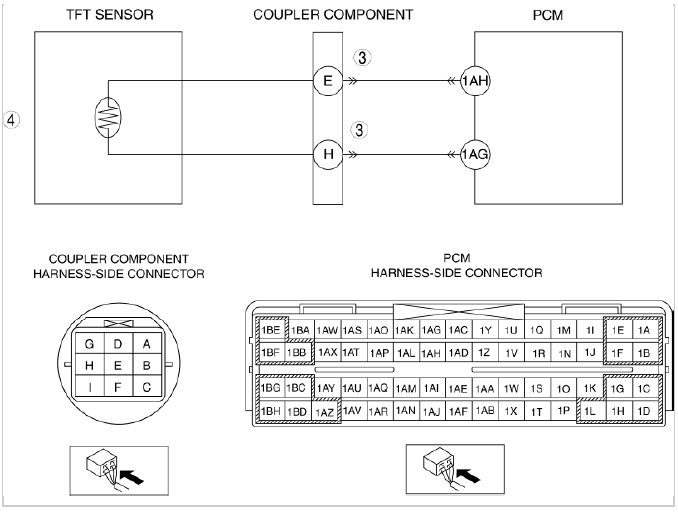
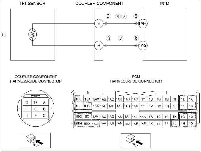
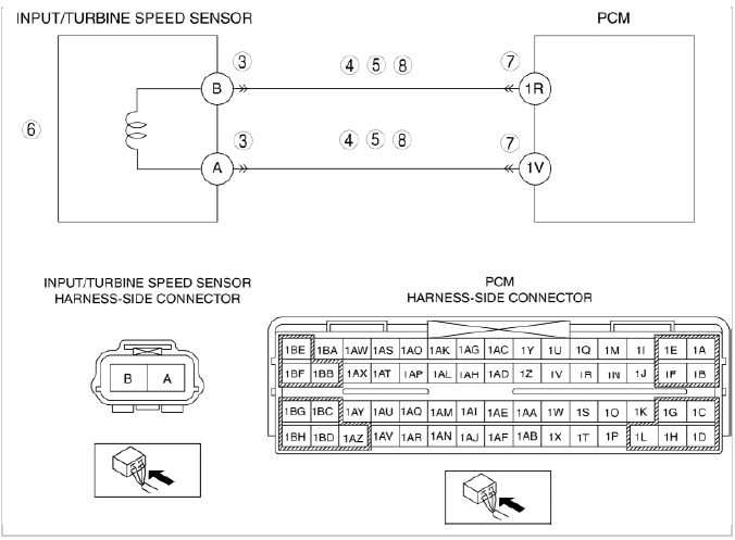
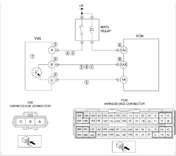
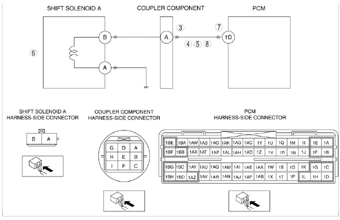
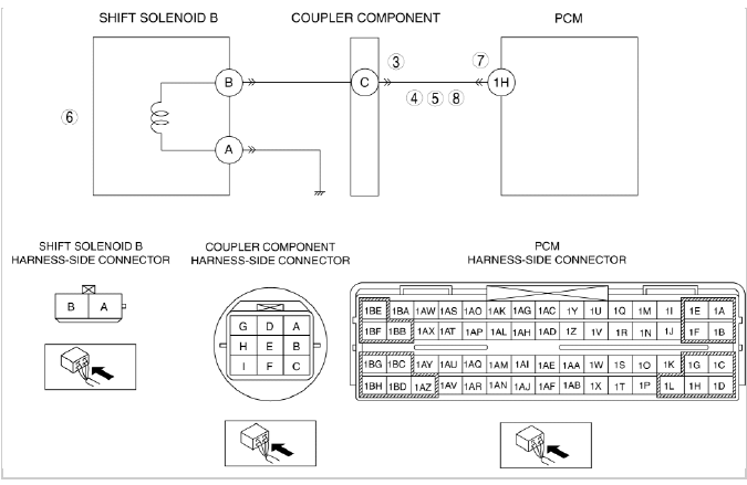
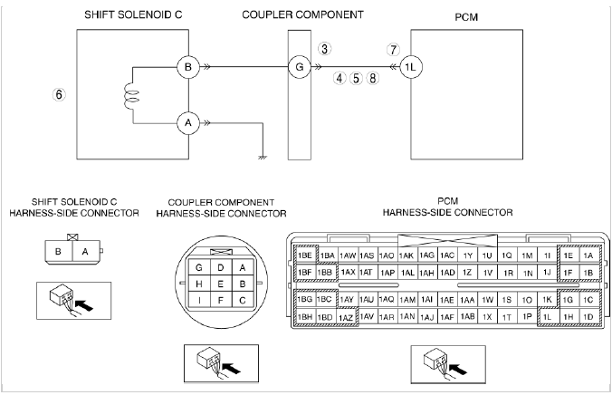
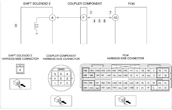
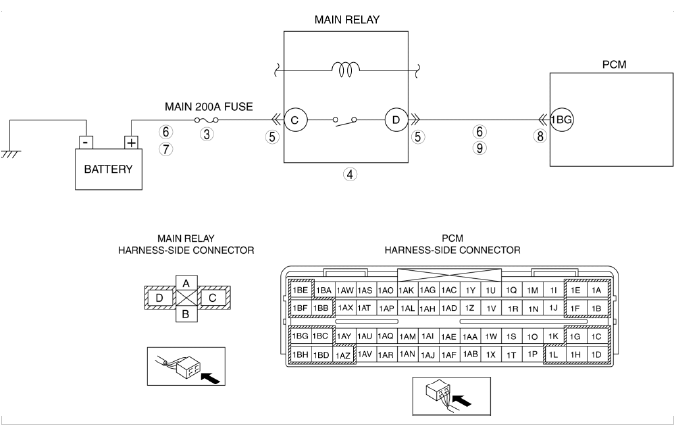
ON-BOARD DIAGNOSTIC SYSTEM WIRING DIAGRAM
NOTE:
- Only the transaxle-related information is described.
ON-BOARD DIAGNOSTIC SYSTEM DTC INSPECTION
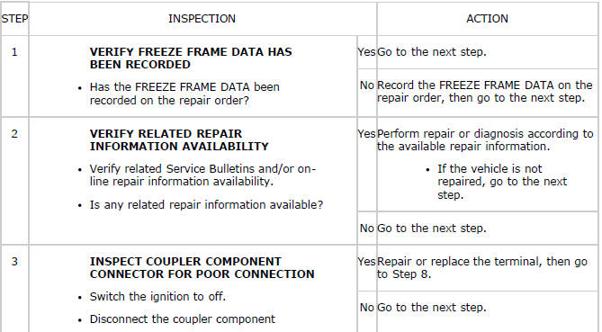
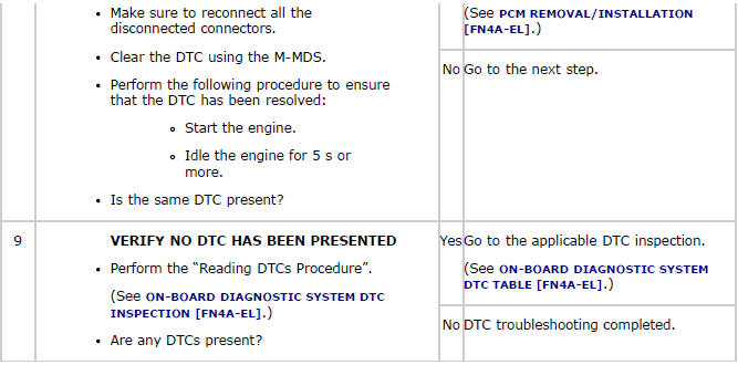
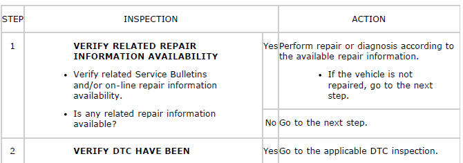
DTC Inspection Procedure (See ON-BOARD DIAGNOSTIC TEST).
DTC Clearing Procedure (See AFTER REPAIR PROCEDURE).
ON-BOARD DIAGNOSTIC SYSTEM DTC TABLE
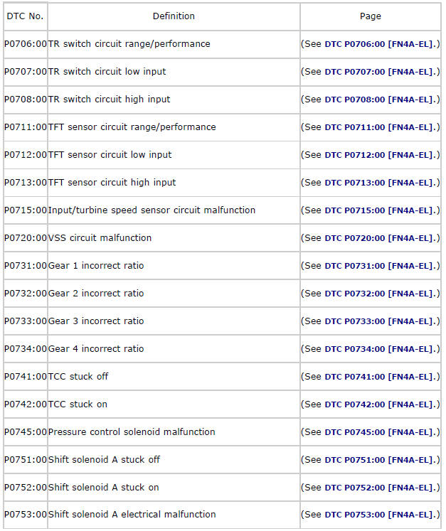
DTC P0706:00
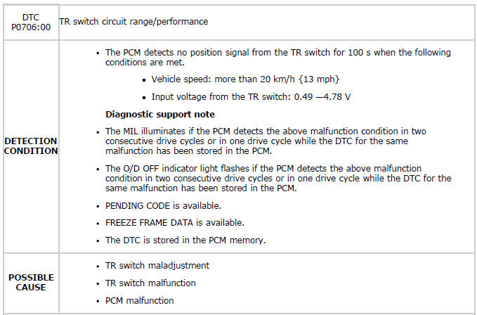
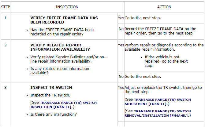
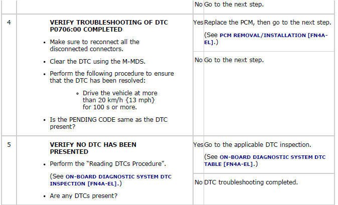
Diagnostic procedure
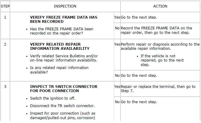
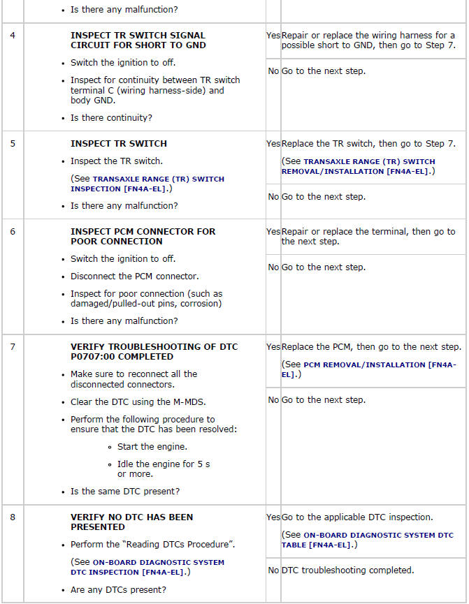
DTC P0707:00
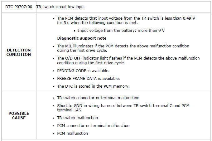
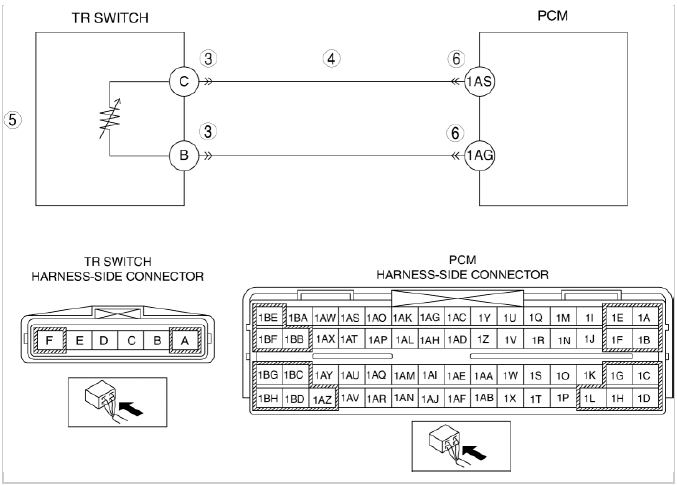
Diagnostic procedure
DTC P0708:00
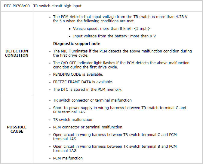
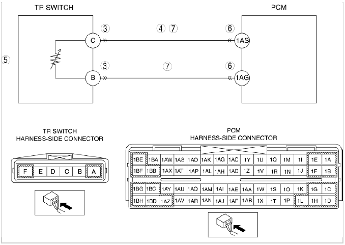
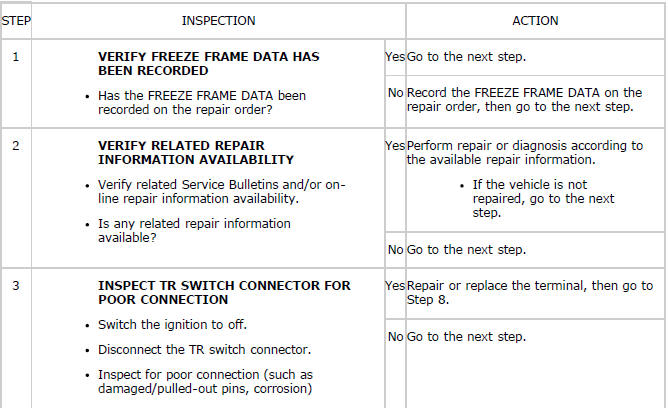
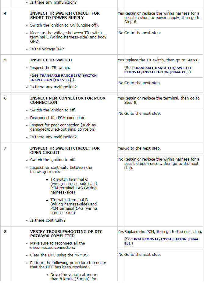
Diagnostic procedure
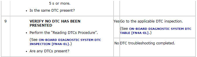
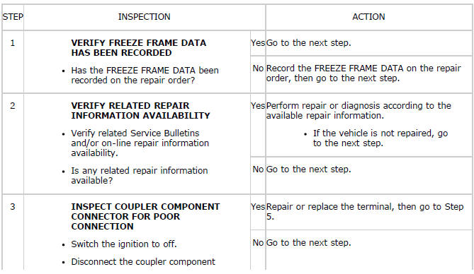
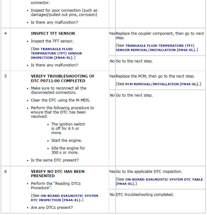
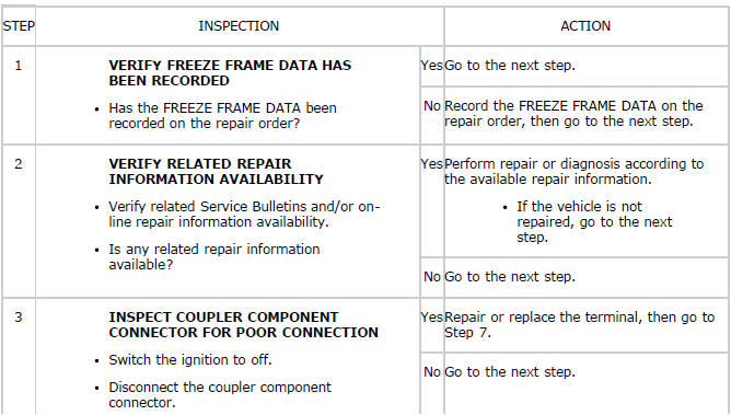
DTC P0711:00
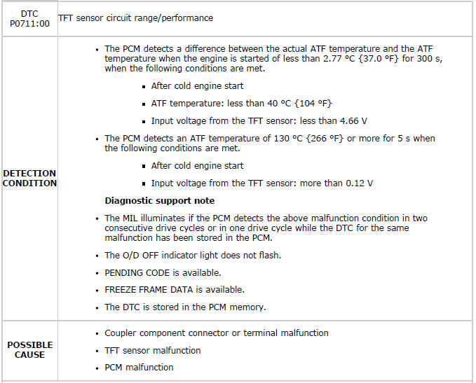
Diagnostic procedure
DTC P0712:00
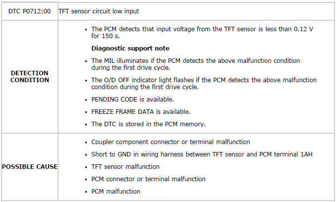
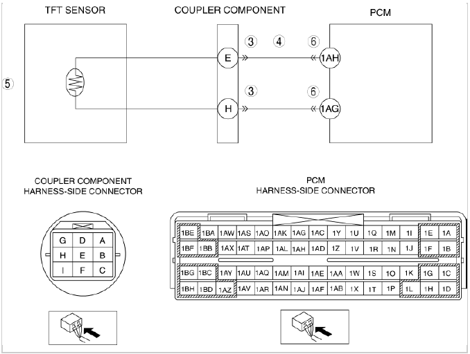
Diagnostic procedure
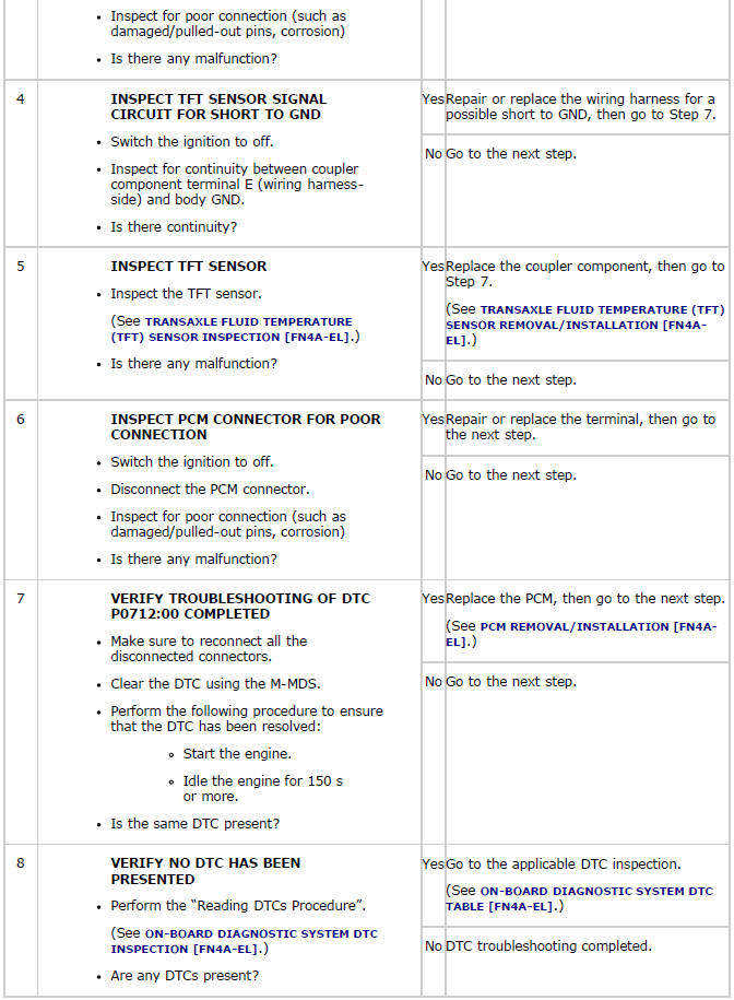
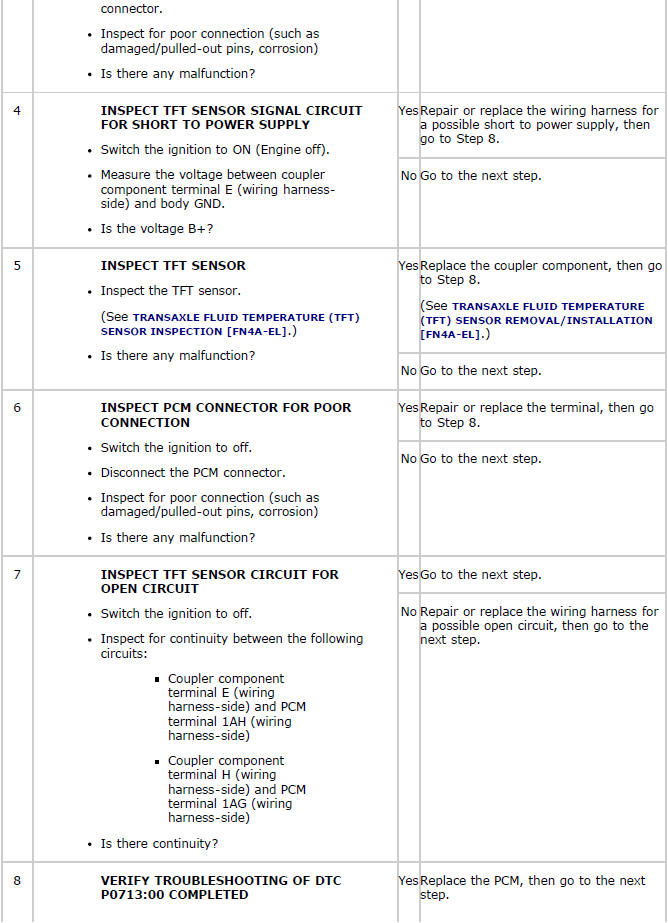
DTC P0713:00
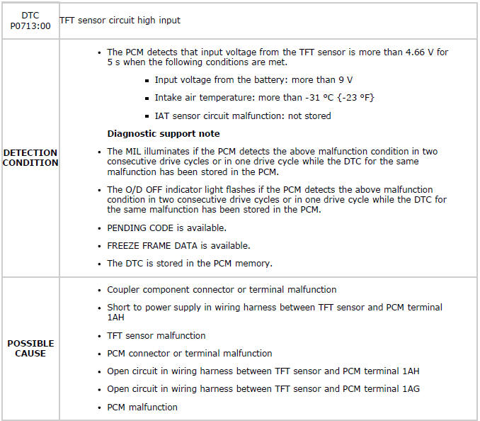
Diagnostic procedure
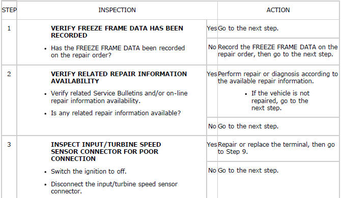
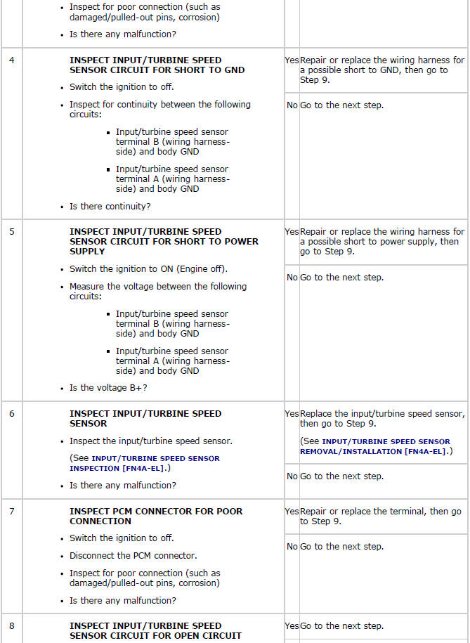
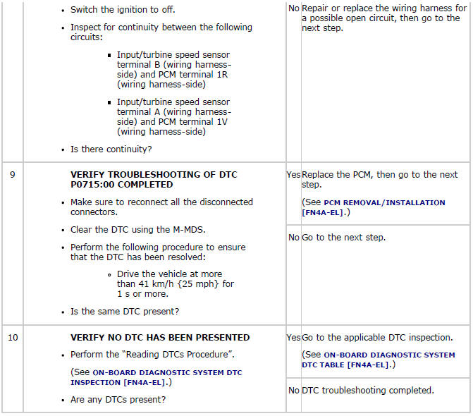
DTC P0715:00
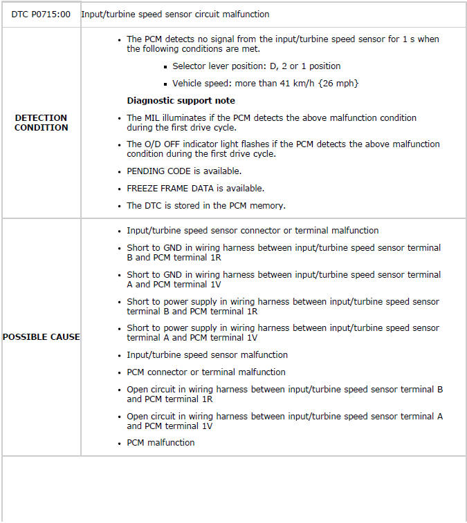
Diagnostic procedure
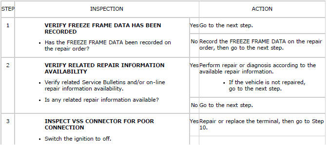
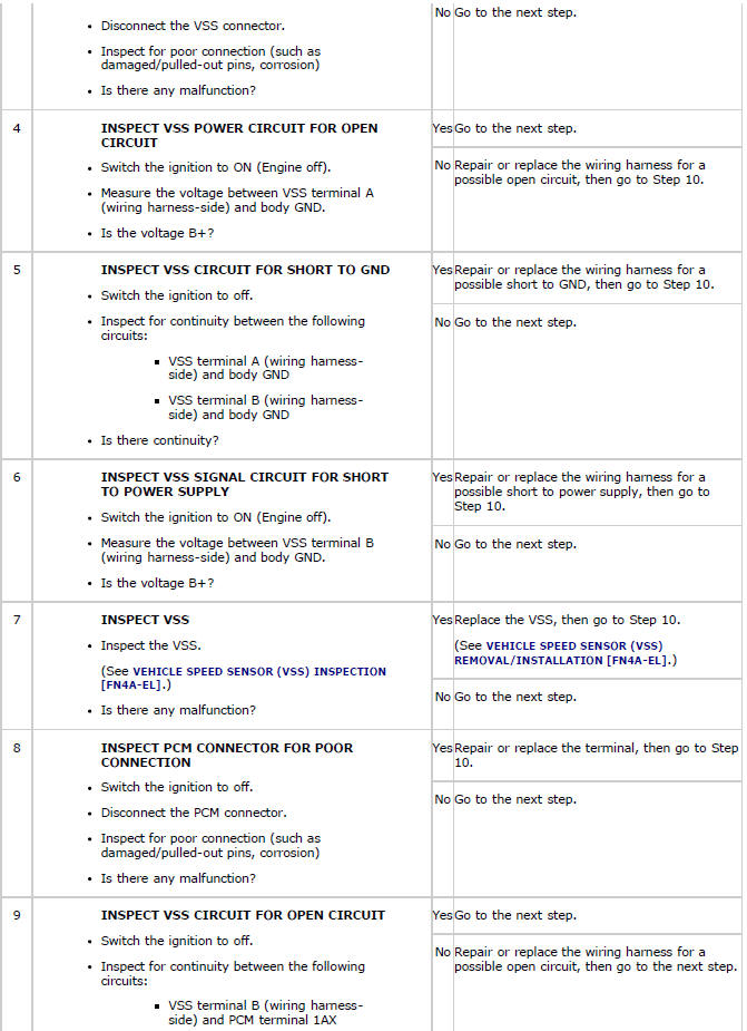
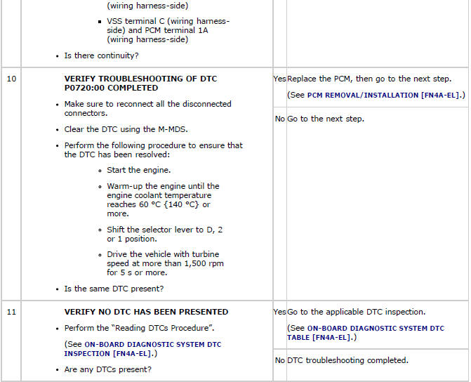
DTC P0720:00
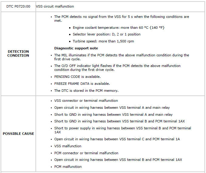
Diagnostic procedure
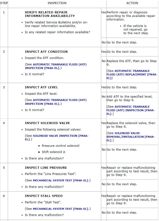
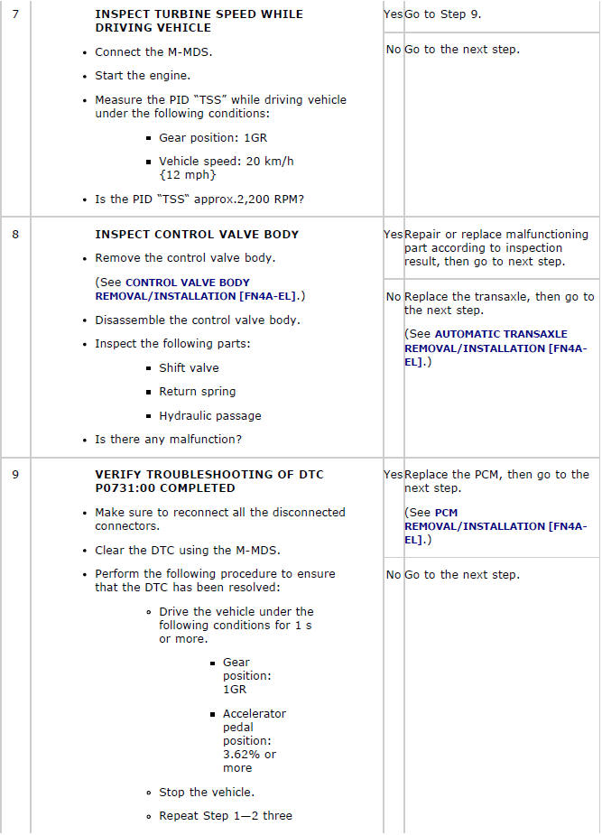
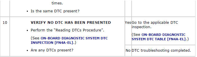
DTC P0731:00
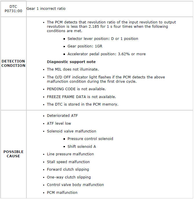
Diagnostic procedure
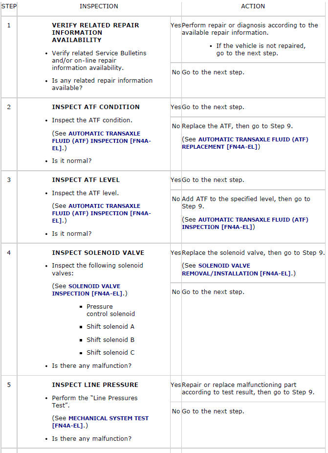
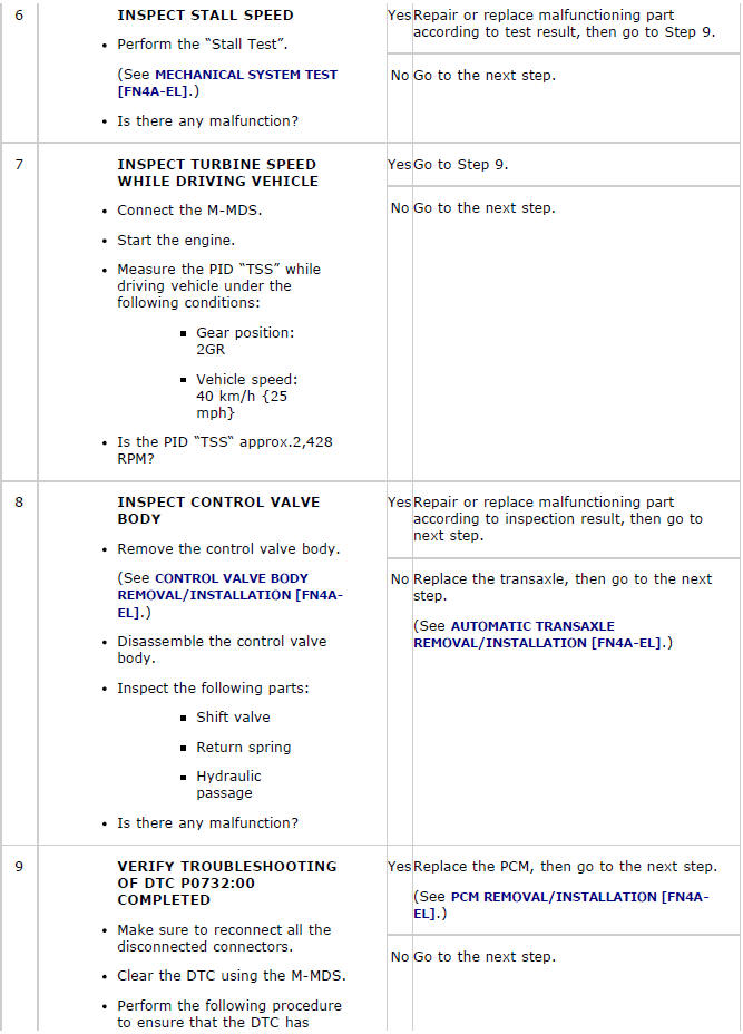
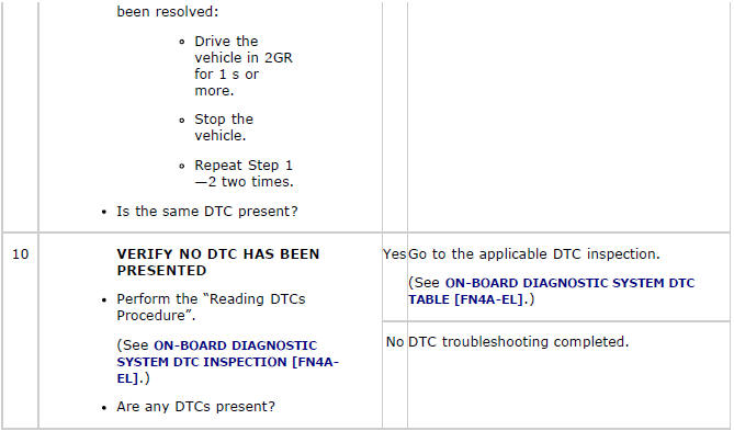
DTC P0732:00
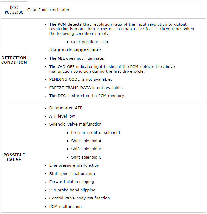
Diagnostic procedure
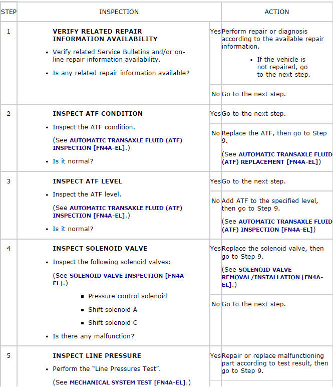
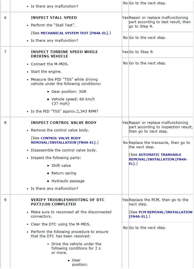
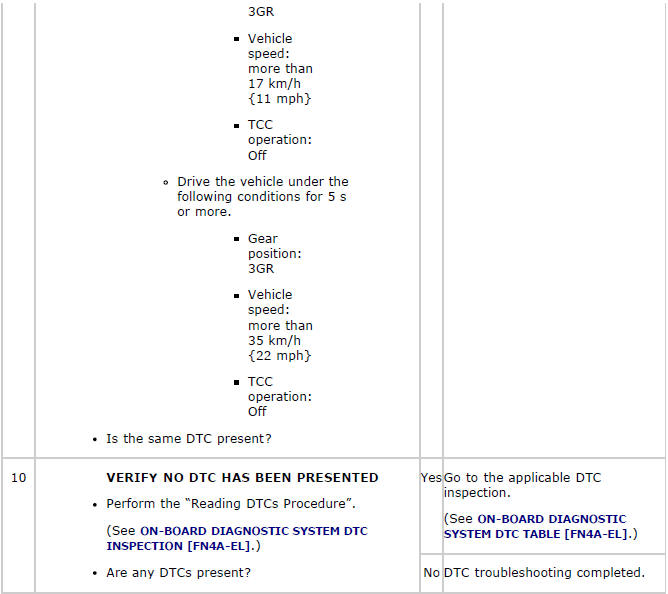
DTC P0733:00
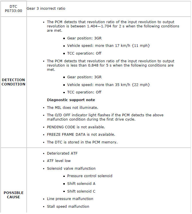

Diagnostic procedure
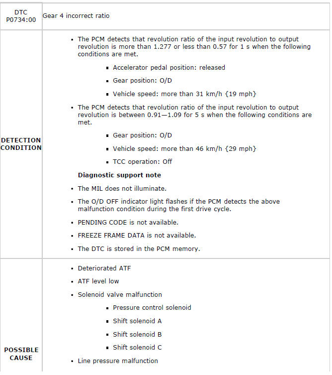
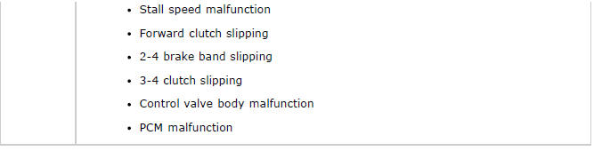
DTC P0734:00
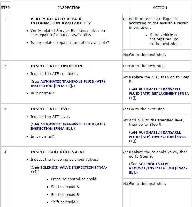
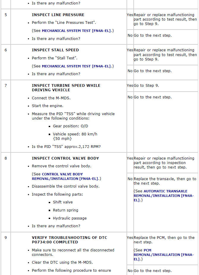
Diagnostic procedure
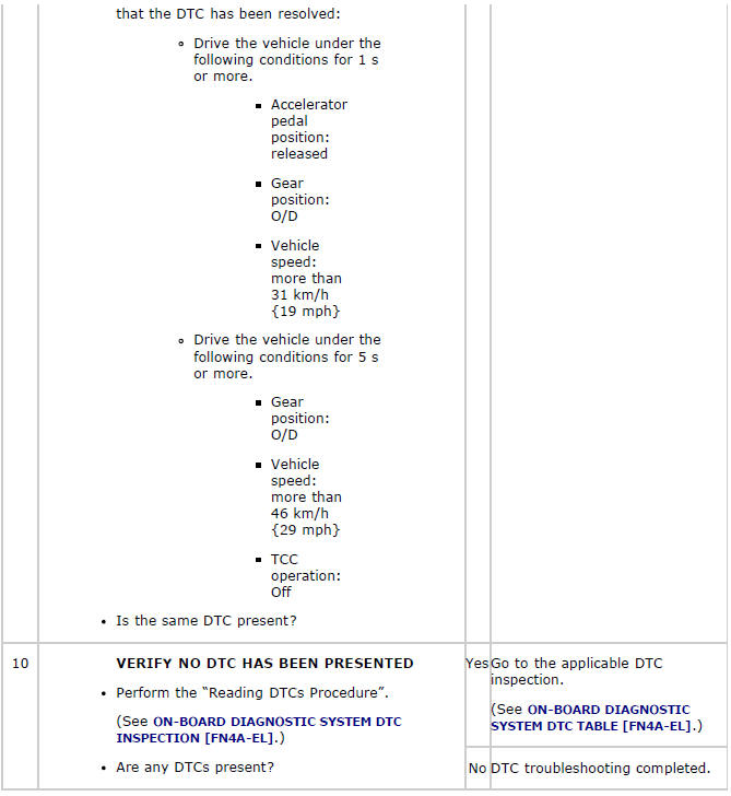
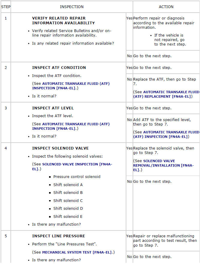
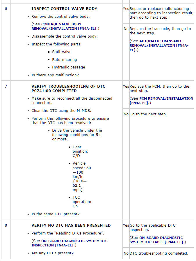
DTC P0741:00
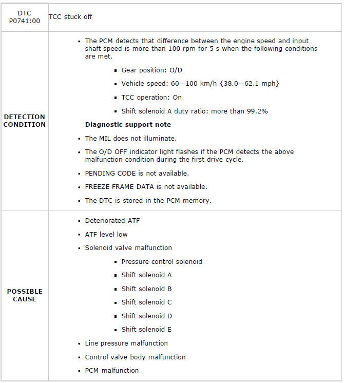
Diagnostic procedure
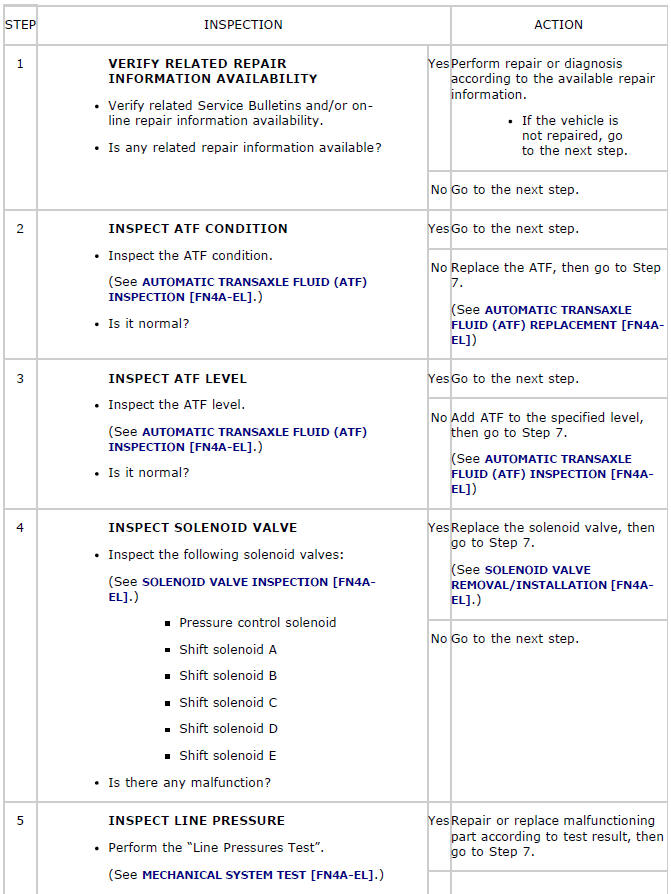
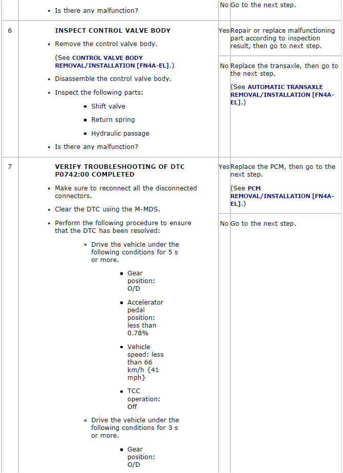
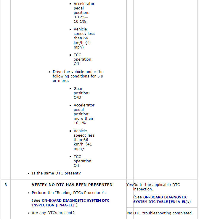
DTC P0742:00
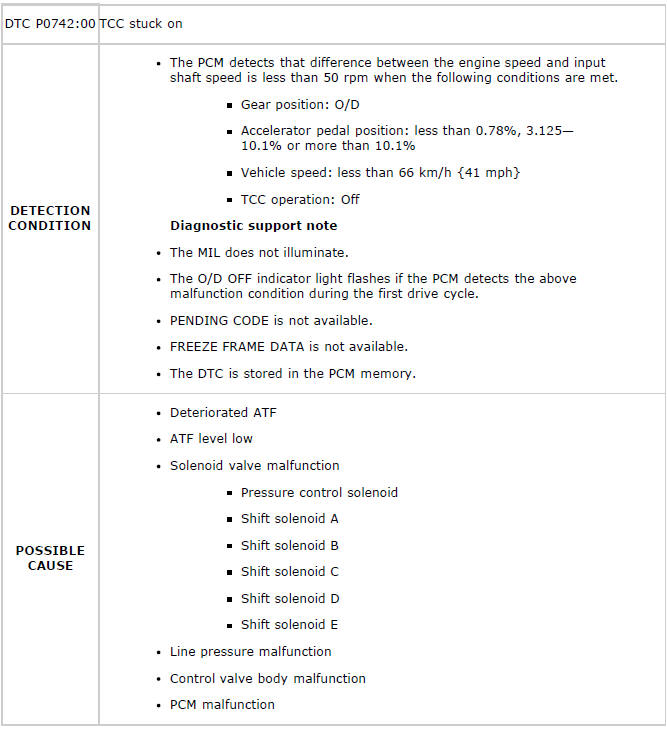
Diagnostic procedure
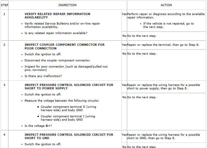
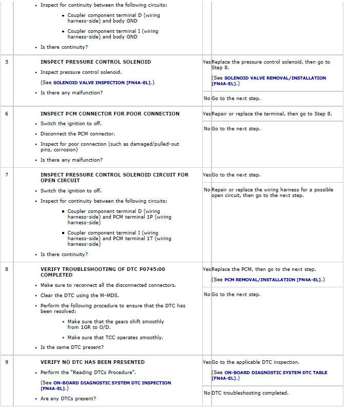
DTC P0745:00
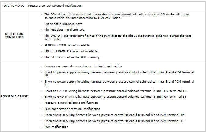
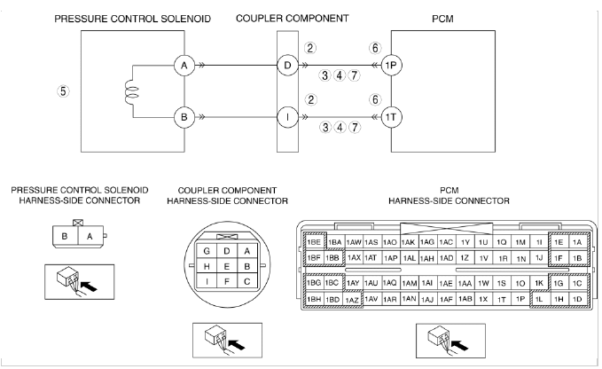
Diagnostic procedure
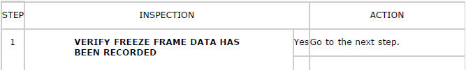
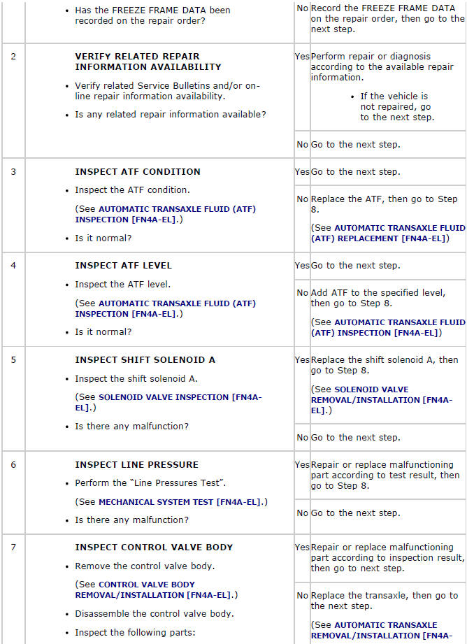
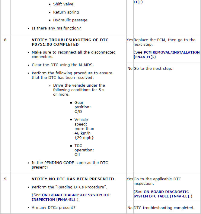
DTC P0751:00
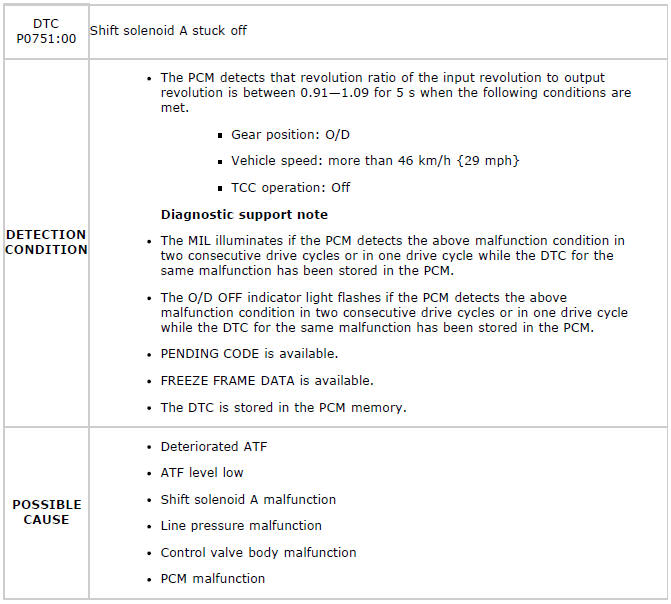
Diagnostic procedure
DTC P0752:00
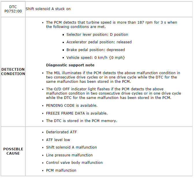
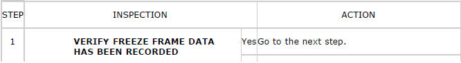
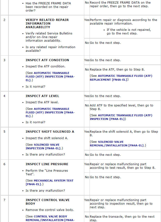
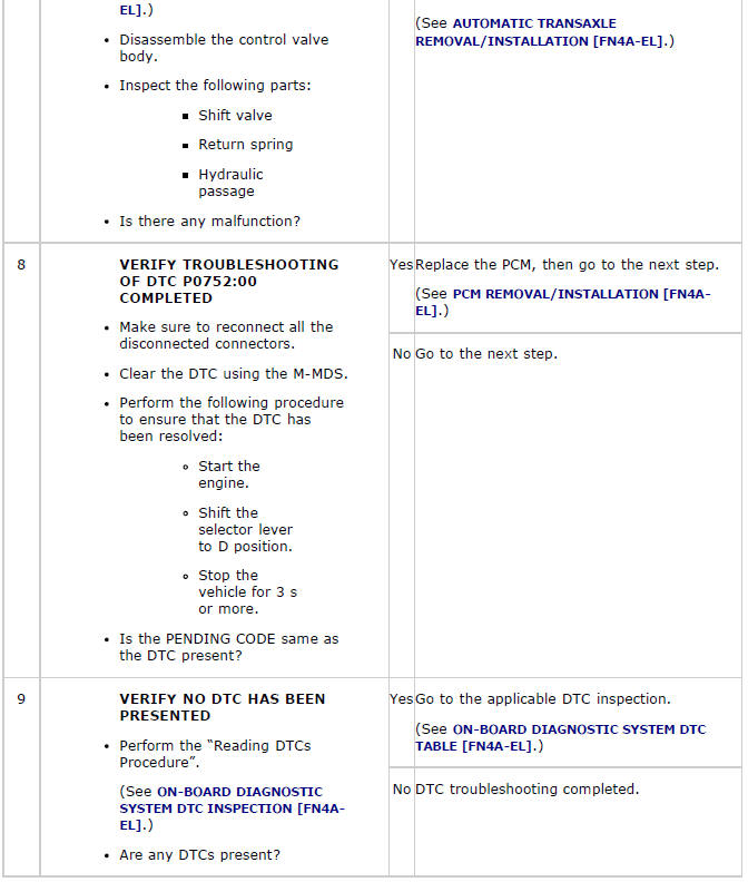
Diagnostic procedure
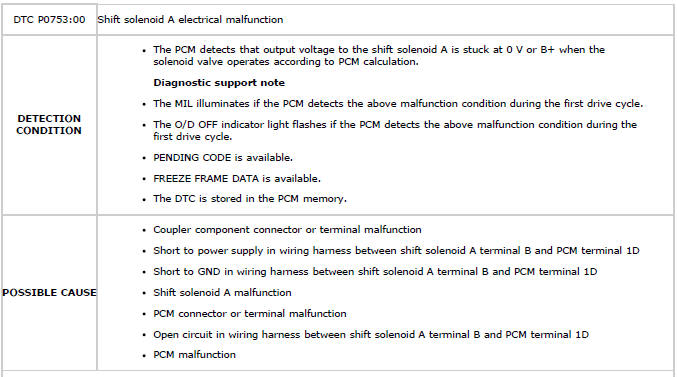
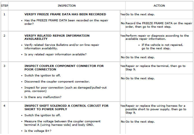
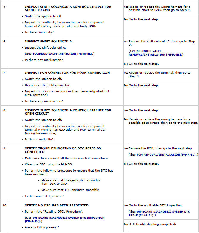
DTC P0753:00
Diagnostic procedure
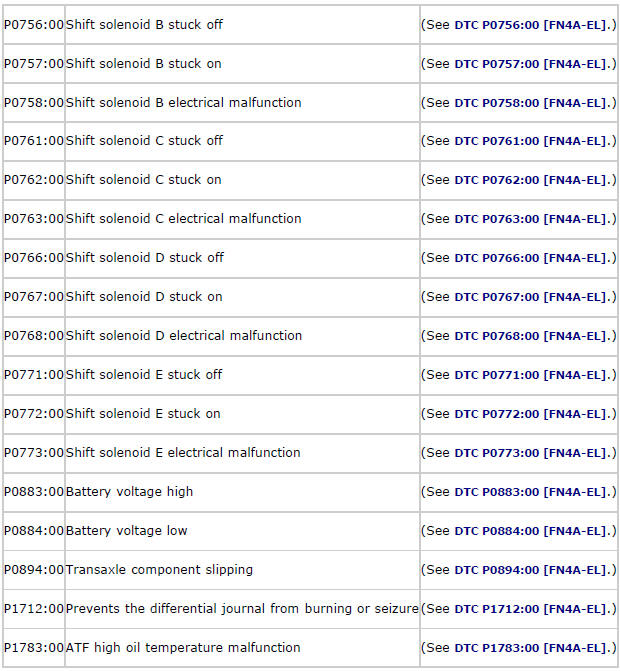
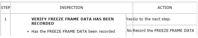
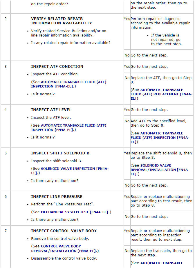
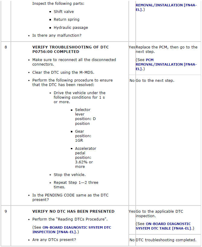
DTC P0756:00
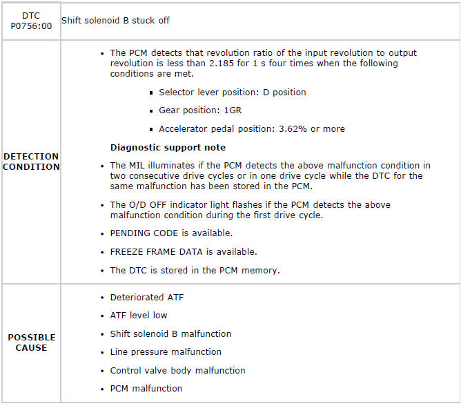
Diagnostic procedure
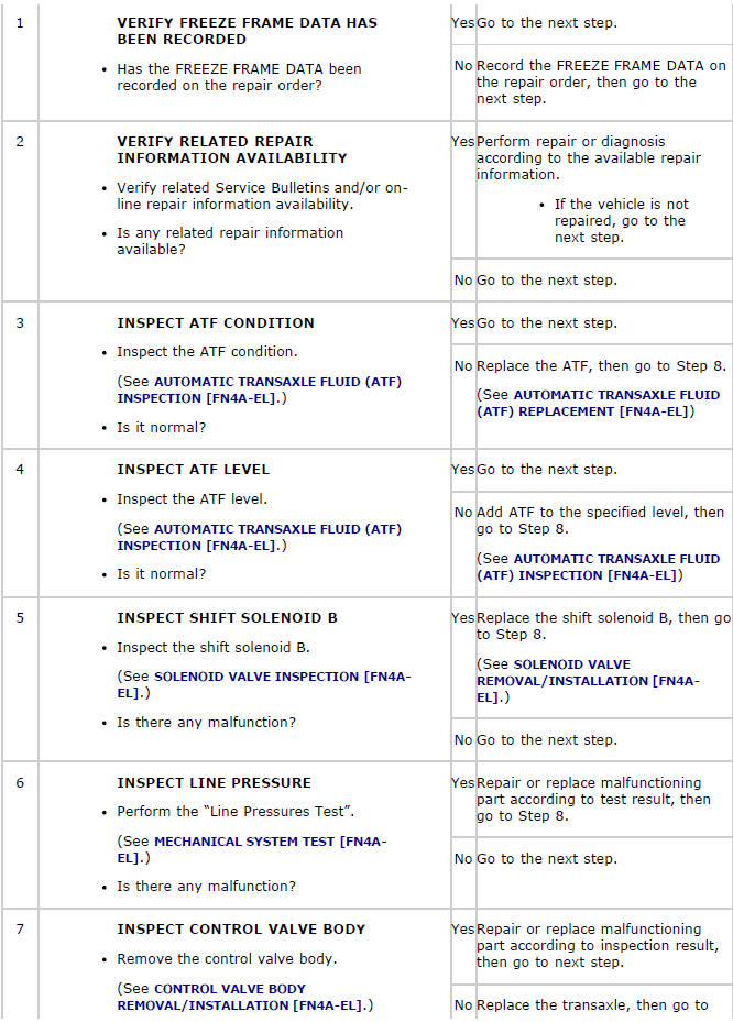
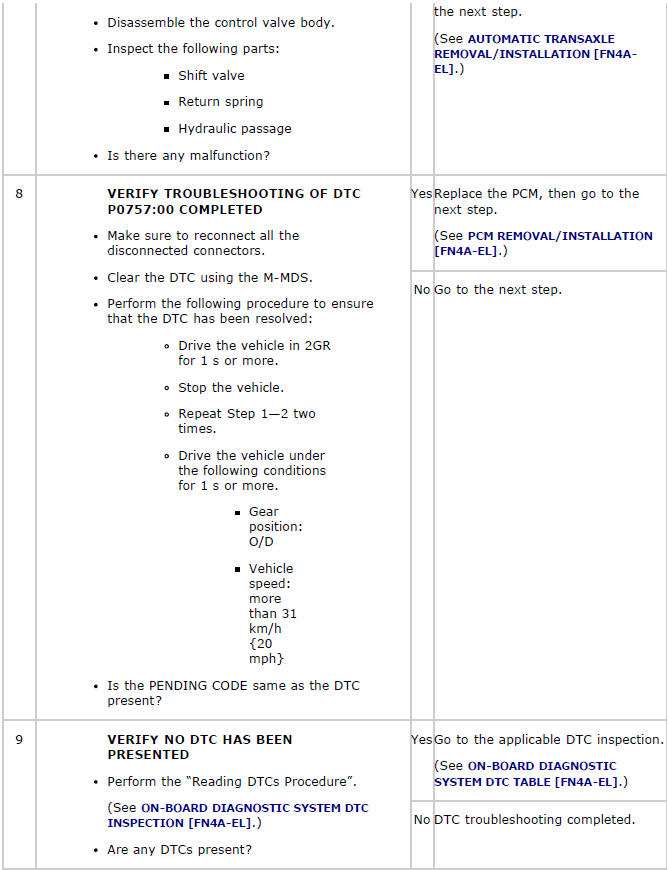
DTC P0757:00
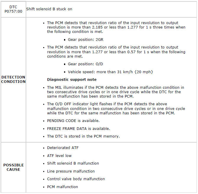
Diagnostic procedure

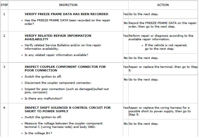
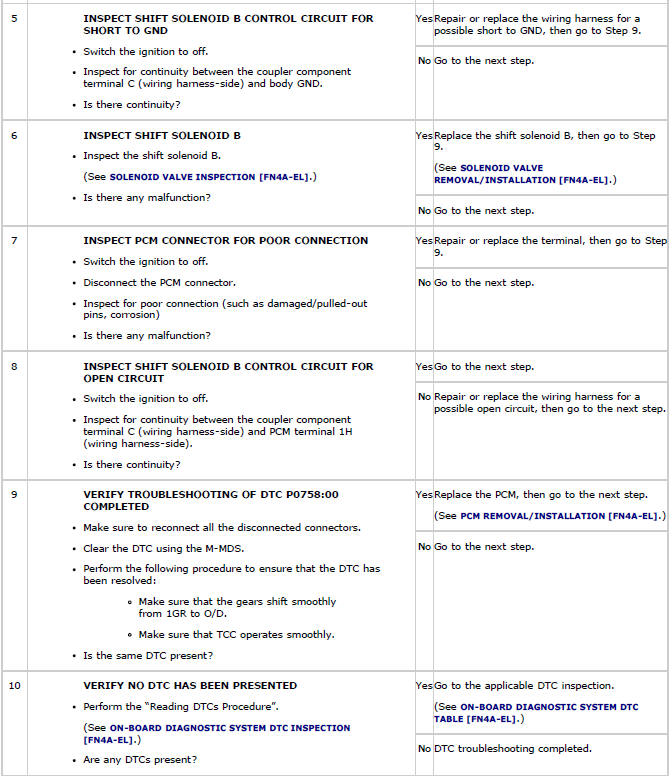
DTC P0758:00
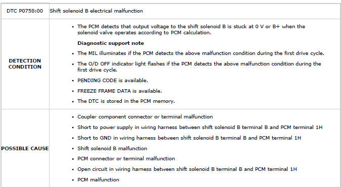
Diagnostic procedure
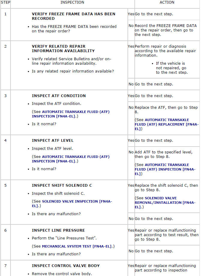
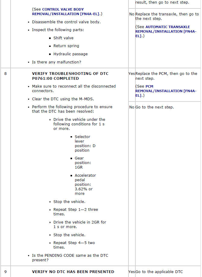
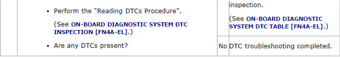
DTC P0761:00
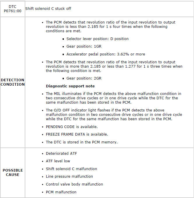
Diagnostic procedure
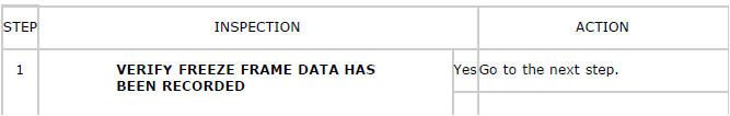
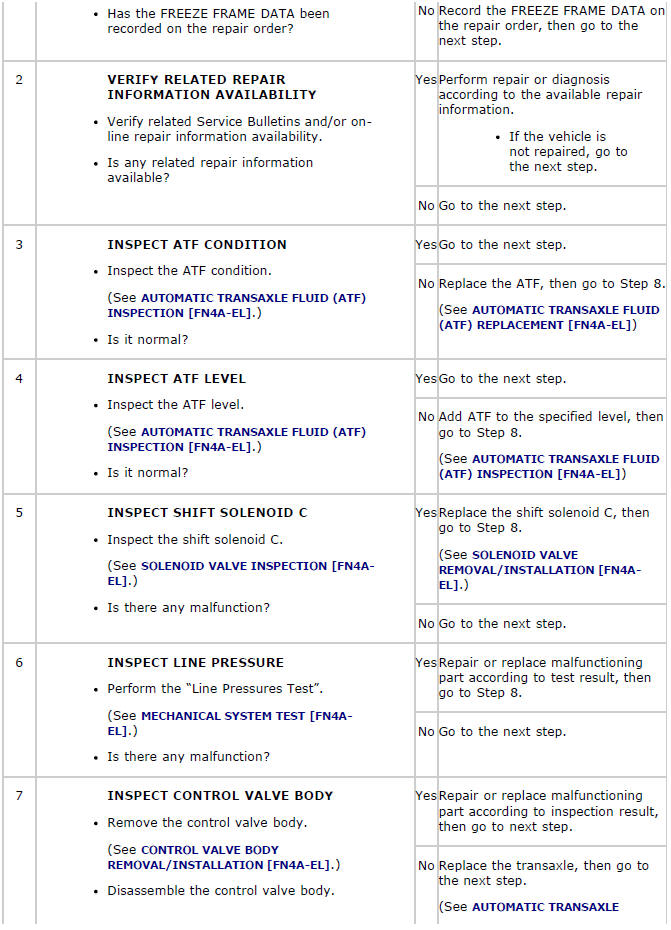
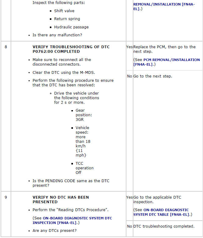
DTC P0762:00
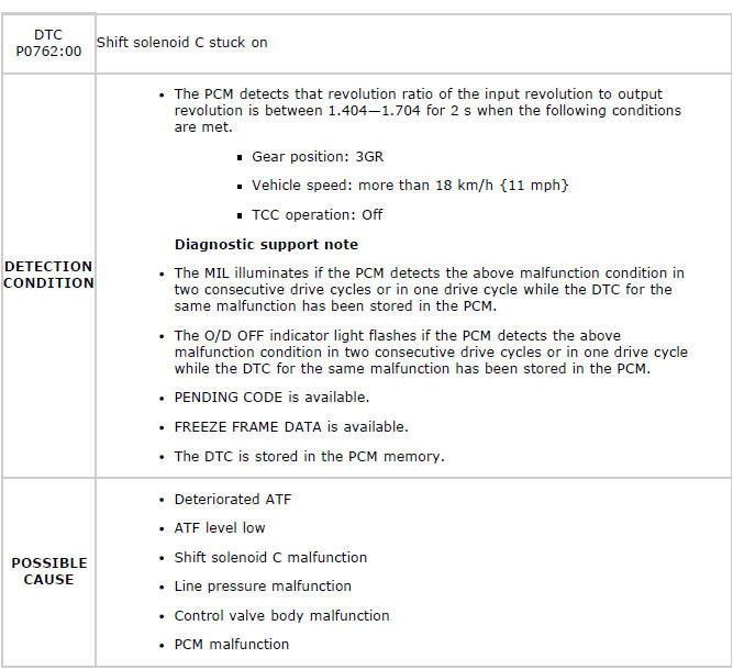
Diagnostic procedure
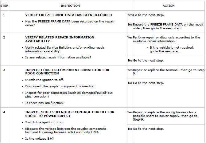
DTC P0763:00

Diagnostic procedure
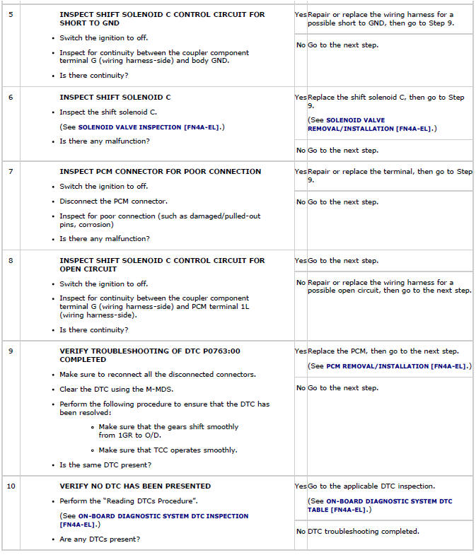
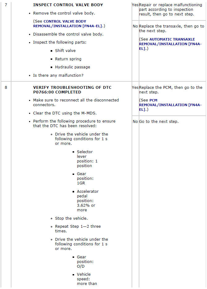
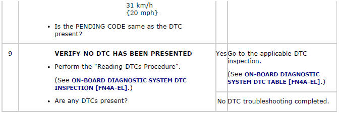
DTC P0766:00
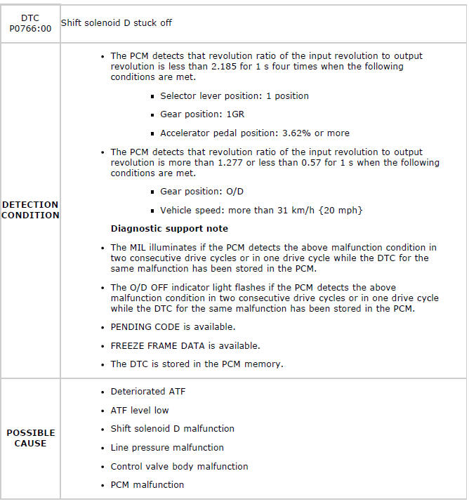
Diagnostic procedure
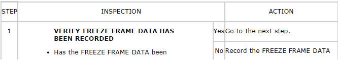
DTC P0767:00
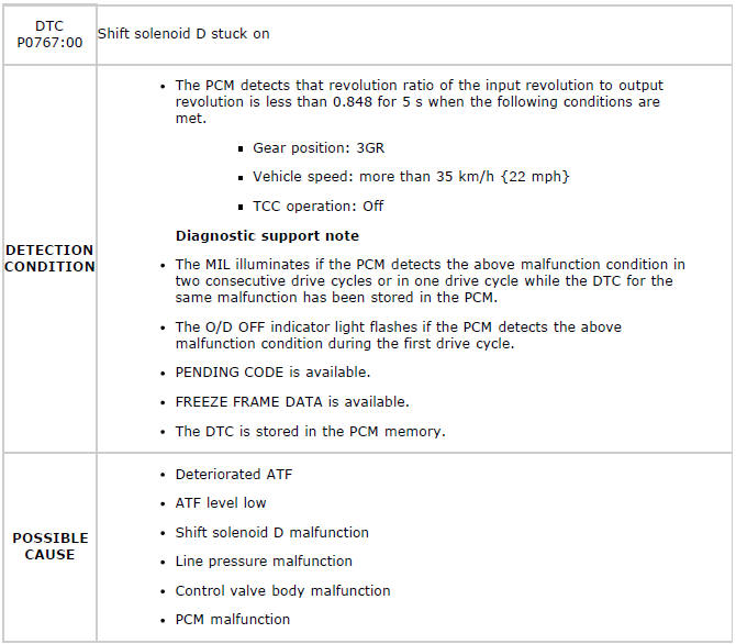
Diagnostic procedure
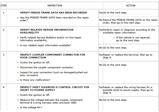
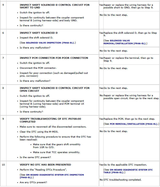
DTC P0768:00
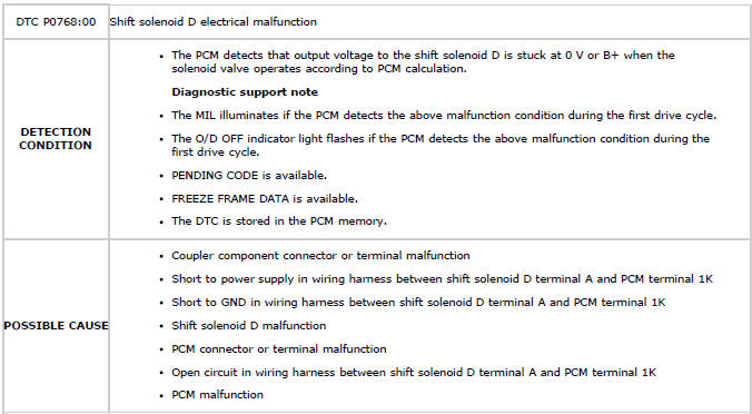
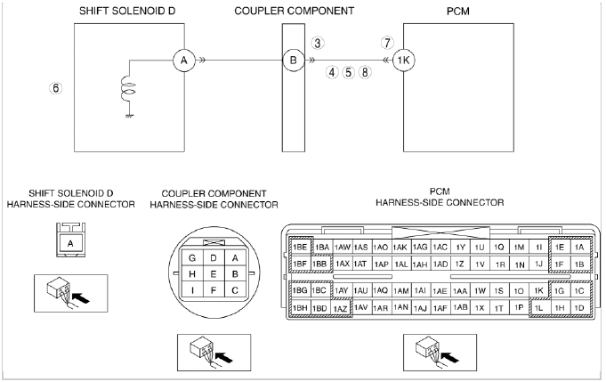
Diagnostic procedure
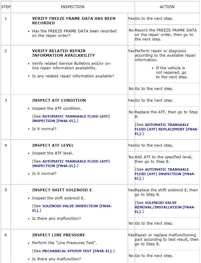
DTC P0771:00
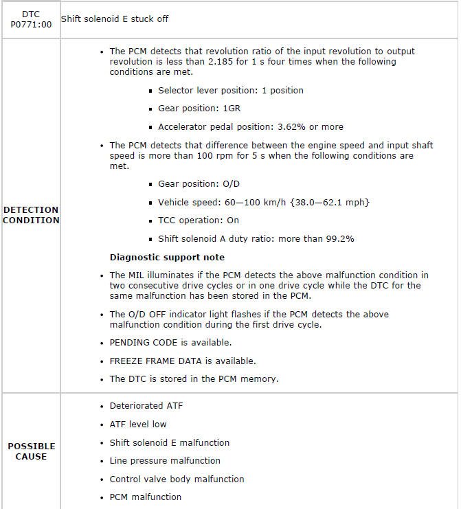
Diagnostic procedure
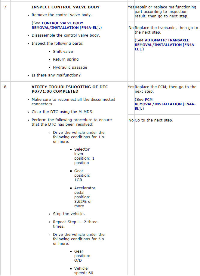
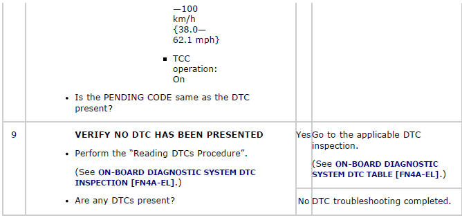
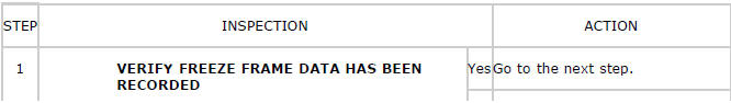
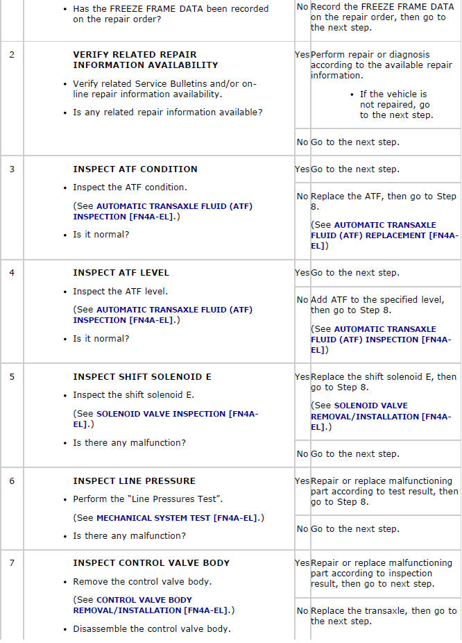
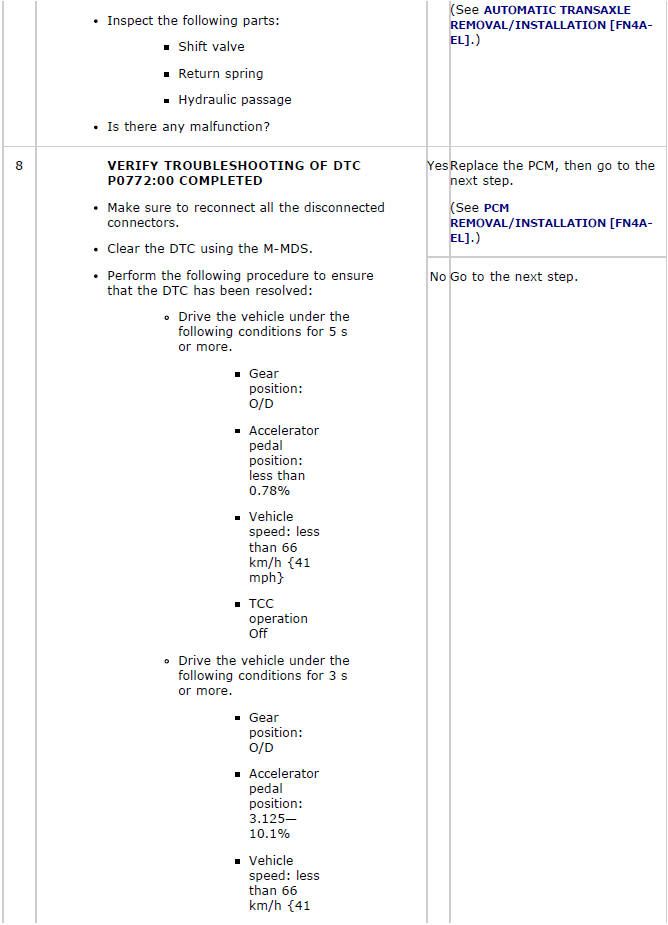
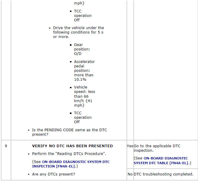
DTC P0772:00
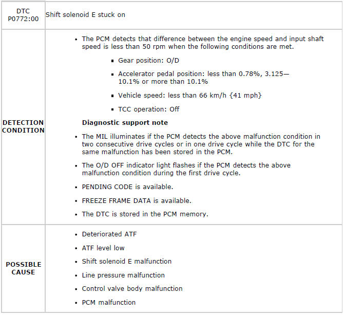
Diagnostic procedure
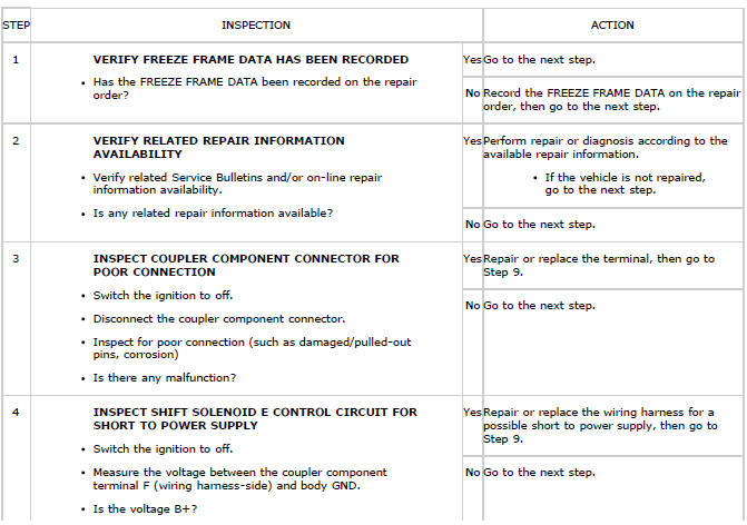
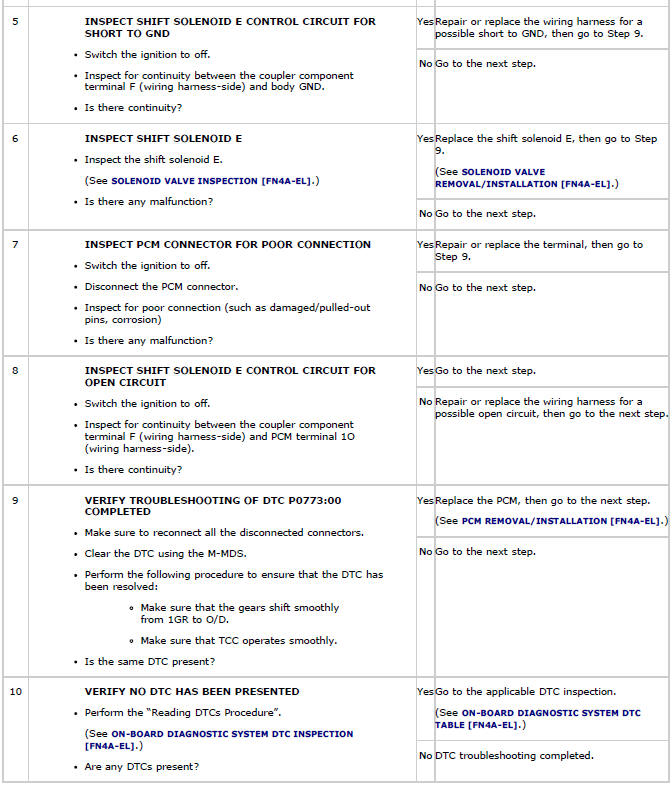
DTC P0773:00
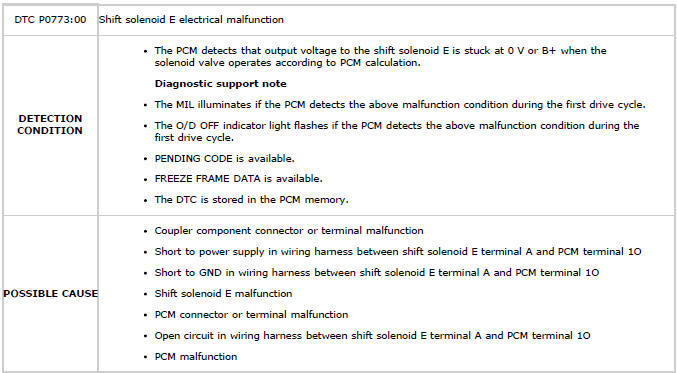
Diagnostic procedure
DTC P0883:00
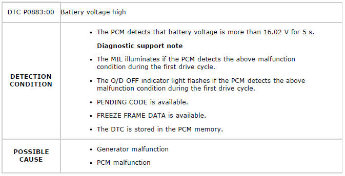
Diagnostic procedure
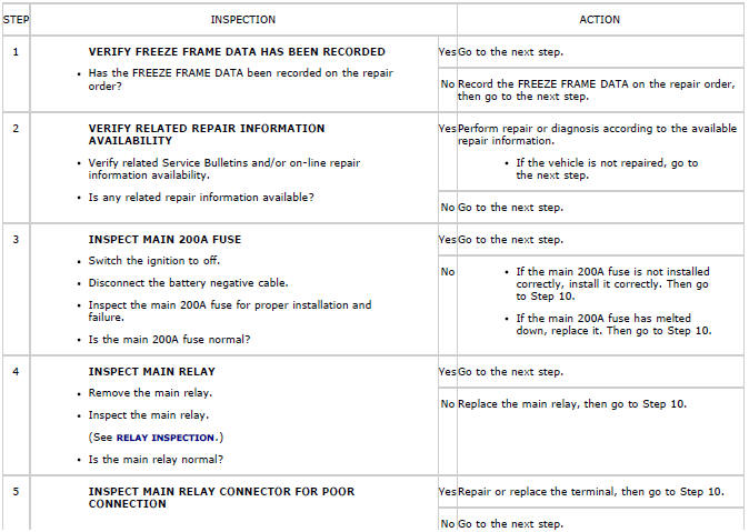
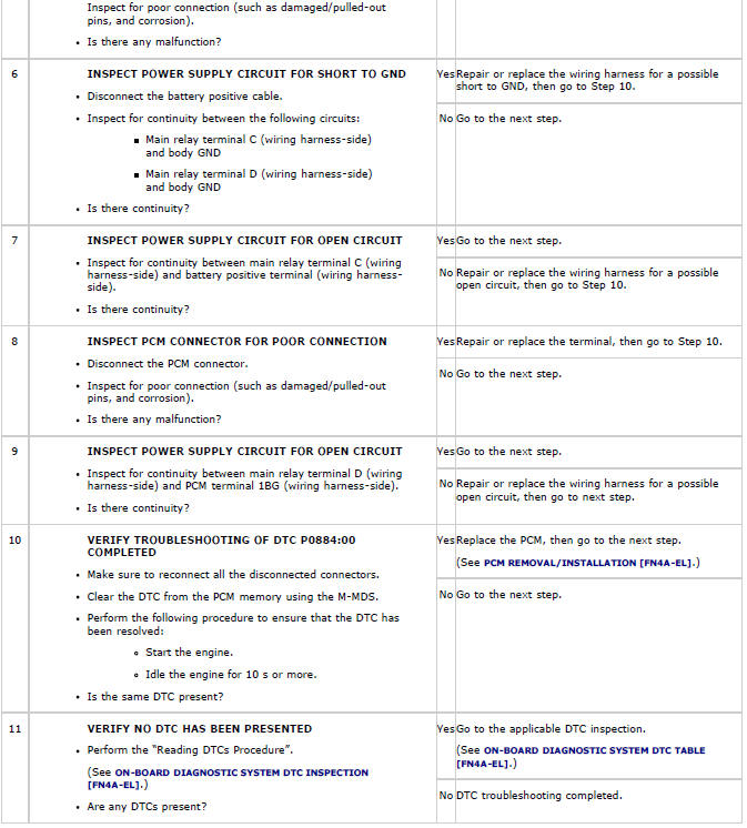
DTC P0884:00
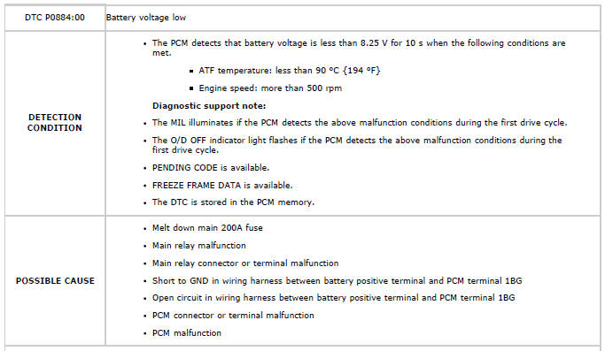
Diagnostic procedure
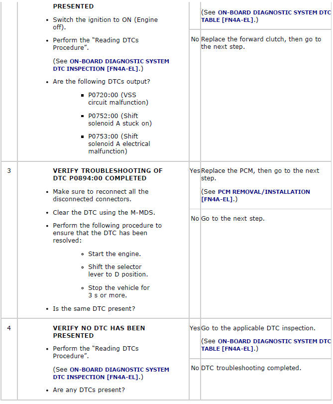
DTC P0894:00
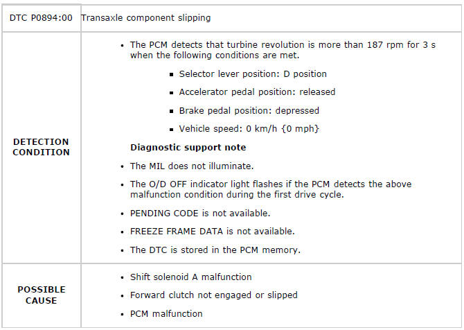
Diagnostic procedure
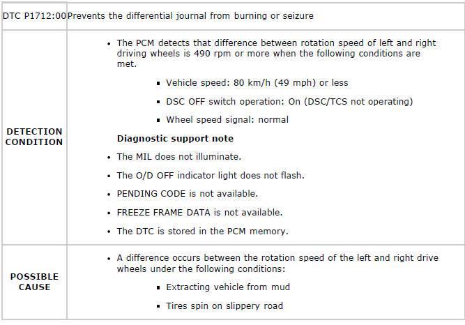
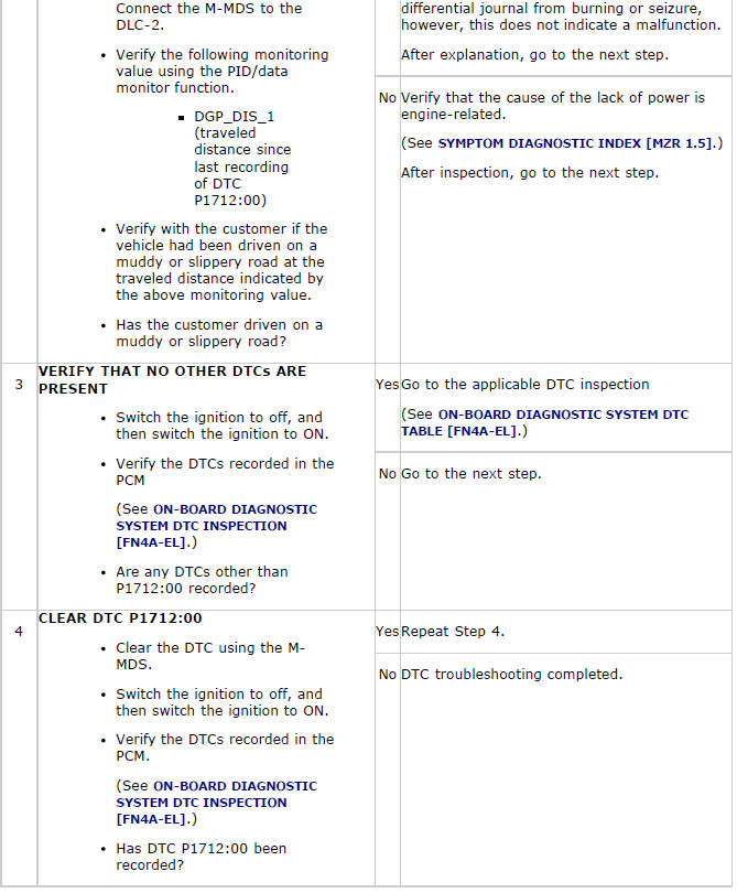
DTC P1712:00
NOTE:
- This DTC is recorded when the torque reduction control operates to prevent the differential journal from burning or seizure. The DTC does not indicate a malfunction.
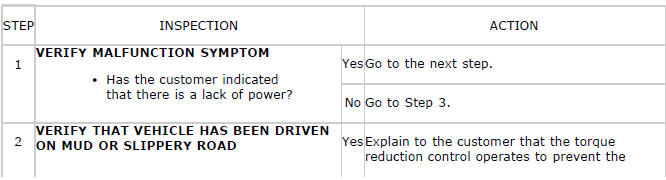
Diagnostic procedure
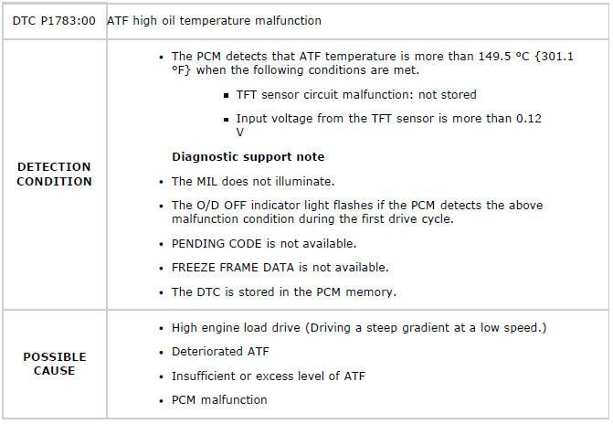
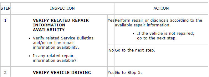
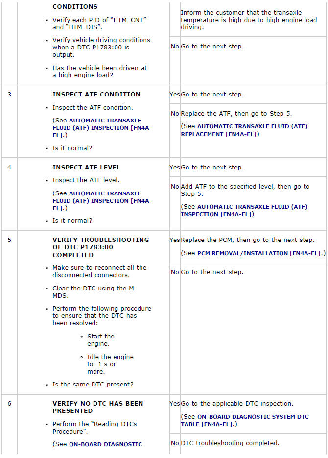
DTC P1783:00
Diagnostic procedure

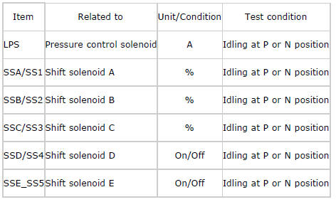
ON-BOARD DIAGNOSTIC SYSTEM PID/DATA MONITOR INSPECTION
NOTE:
- The PID data screen function is used for monitoring the calculated value of input/output signals in the module. Therefore, if the monitored value of the output parts is not within the specification, it is necessary to inspect the monitored value of input parts corresponding to the applicable output part control. In addition, because the system does not display an output part malfunction as an abnormality in the monitored value, it is necessary to inspect the output parts individually.
1. Connect the M-MDS(IDS) to the DLC-2.
2. After the vehicle is identified, select the following items from the initialization screen of the IDS.
- Select "DataLogger".
- Select "Modules".
- Select "PCM".
3. Select the applicable PID from the PID table.
4. Verify the PID data according to the detections on the screen.
NOTE:
- Only the transaxle-related information is described.
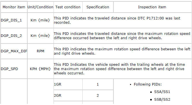
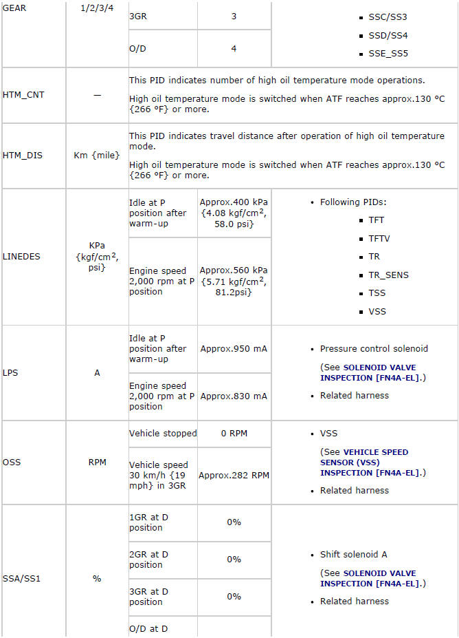
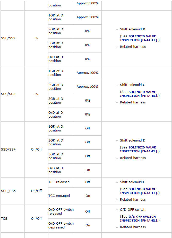
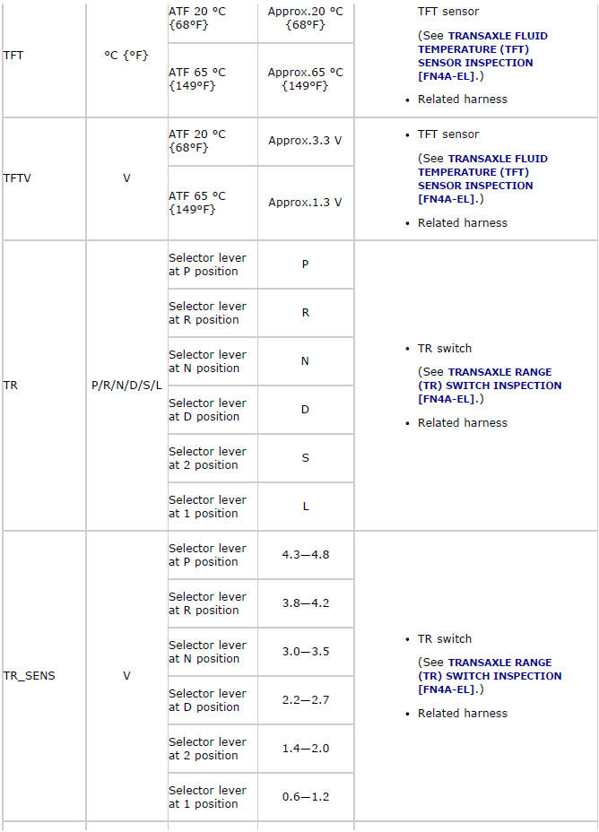
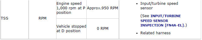
PID/DATA Monitor Table (Reference)
ON-BOARD DIAGNOSTIC SYSTEM SIMULATION INSPECTION
1. Connect the M-MDS(IDS) to the DLC-2.
2. After the vehicle is identified, select the following items from the initialization screen of the IDS.
- Select "DataLogger".
- Select "Modules".
- Select "PCM".
3. Select the simulation items from the PID table.
4. Perform the active command modes function, inspect the operations for each parts.
- If the operation of output parts cannot be verified after the active command mode inspection is performed, this could indicate the possibility of an open or short circuit, sticking, or operation malfunction in the output parts.
NOTE:
- Only the transaxle-related information is described.
Simulation table