Mazda 2: Clutch
CLUTCH LOCATION INDEX
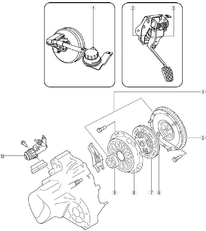
- Reserve tank
- (See CLUTCH FLUID INSPECTION)
- (See CLUTCH FLUID AIR BLEEDING/REPLACEMENT)
- Clutch master cylinder
- (See CLUTCH MASTER CYLINDER REMOVAL/INSTALLATION)
- Clutch pedal
- (See CLUTCH PEDAL INSPECTION)
- (See CLUTCH PEDAL REMOVAL/INSTALLATION)
- Clutch unit
- (See CLUTCH UNIT REMOVAL/INSTALLATION)
- Flywheel
- (See FLYWHEEL INSPECTION)
- Pilot bearing
- (See PILOT BEARING INSPECTION)
- Clutch disc
- (See CLUTCH DISC INSPECTION)
- Clutch cover
- (See CLUTCH COVER INSPECTION)
- Clutch release collar
- (See CLUTCH RELEASE COLLAR INSPECTION)
- Clutch release cylinder
- (See CLUTCH RELEASE CYLINDER REMOVAL/INSTALLATION)
GENERAL PROCEDURES (CLUTCH)
CAUTION:
- If clutch pipes have been disconnected any time during the procedure, add clutch fluid (brake fluid), bleed the air, and inspect for leakage after the procedure has been completed.
NOTE:
- A common reserve tank is used for the clutch and brake system fluid.
CLUTCH FLUID INSPECTION
NOTE:
- A common reserve tank is used for the clutch and brake system fluid.
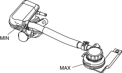
- The fluid in the reserve tank must be maintained between the MIN/MAX level during replacement.
CLUTCH FLUID AIR BLEEDING/REPLACEMENT
CAUTION:
- Fluid will damage painted surfaces. Be careful not to spill any on painted surfaces. If it is spilled, wipe it off immediately.
- Keep the fluid level in the reserve tank at 3/4 full or more during the air bleeding.
- Do not mix different types of fluid, otherwise the clutch may not operate normally.
- Do not reuse old fluid, otherwise the clutch may not operate normally.
NOTE:
- When replacing the fluid, drain the old fluid, fill the reserve tank with new fluid and then perform Steps 1-7 below.
Clutch fluid
- SAE J1703 or FMVSS116 DOT-3
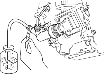
1. Remove the bleeder cap from the clutch release cylinder, and connect a vinyl hose to the bleeder plug.
2. Place the other end of the vinyl hose in a clear container, and fill fluid in the container during air bleeding.
3. Working with two people, one should depress the clutch pedal a few times and then depress and hold the pedal down.
4. While the clutch pedal is being held down, the other person should loosen the bleeder screw using the commercially available flare nut wrench, and bleed any fluid containing air bubbles. Once completed, tighten the bleeder screw.
5. Continue to perform Steps 3 and 4 until no air comes from the vinyl hose.
6. Tighten the bleeder screw to the specified torque.
Tightening torque
- 5.9-8.8 N*m {61-89 kgf*cm, 53-77 in*lbf}
7. Install the bleeder cap.
8. Fill the reserve tank to MAX with the recommended fluid.
9. Perform the following inspections:
- Clutch operation
- Clutch fluid leakage
- Clutch fluid level
CLUTCH PEDAL INSPECTION
Clutch Pedal Height Inspection
1. Measure the distance from the center of the upper surface of the pedal pad to the floor covering.
- If the clutch pedal height is not within the specification, replace the clutch pedal. (See CLUTCH PEDAL REMOVAL/INSTALLATION).
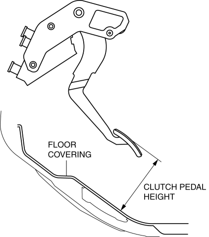
Clutch pedal height (Reference value)
- 123 mm {4.84 in}
Clutch Pedal Free Play Inspection
1. Depress the clutch pedal by hand until clutch resistance is felt.
- If the clutch pedal free play is not within the specification, replace the clutch pedal. (See CLUTCH PEDAL REMOVAL/INSTALLATION).
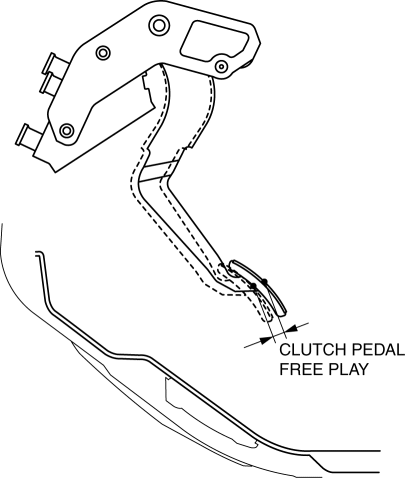
Clutch pedal free play (Reference value)
- 11 mm {0.43 in} or less
Clutch Pedal Disengagement Point Inspection
WARNING:
- When performing the following procedure, make sure that the area around the vehicle is free of people or objects as the vehicle might move suddenly.
1. Apply the parking brake and fix the front and rear of the wheels with the wheel chocks.
2. Start the engine.
3. With the clutch pedal depressed, move the shift lever to the position just before engaging the reverse gear. (Do not shift completely to reverse position) 4. Gradually release the clutch pedal and then hold it at the point where the sound of gear-grinding begins (clutch disengagement point).
5. Depress the clutch pedal slowly.
6. Hold the pedal when the gear noise stops (clutch pedal disengagement point).
7. Measure distance A (the distance from the clutch pedal disengagement point to the fully depressed position) and the pedal stroke.
- If the measurement is not within the specification, inspect the clutch fluid level and the fluid lines for air infiltration.
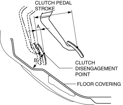
Distance A, from clutch disengagement point to full stroke (Reference value)
- 15 mm {0.59 in} or more
Distance B, from clutch disengagement point to floor covering (Reference value)
- 62 mm {2.4 in} or more
Clutch pedal stroke (Reference value)
- 125 mm {4.92 in}
CLUTCH PEDAL REMOVAL/INSTALLATION
CAUTION:
- Fluid will damage painted surfaces. Be careful not to spill any on painted surfaces. If it is spilled, wipe it off immediately.
- If clutch system-related hydraulic parts are removed, supply brake fluid, bleed air, and inspect for fluid leakage after the installation.
1. Disconnect the negative battery cable. (See BATTERY REMOVAL/INSTALLATION).
2. Remove the battery clamp and battery box and battery. (See BATTERY REMOVAL/INSTALLATION).
3. Remove in the order indicated in the table.
4. Plug the clutch pipe after removing it to avoid leakage.
5. Install in the reverse order of removal.
6. Fully depress the clutch pedal, and verify that the engine starts.
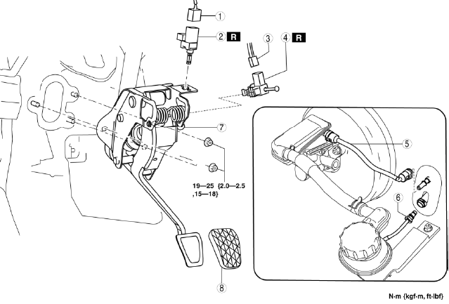
- Clutch pedal position switch connector
- Clutch pedal position switch
- Starter interlock switch connector
- Starter interlock switch
- Reserve hose
- Clutch pipe
- Clutch pedal component
- Pedal pad
Reserve Hose Removal Note
1. Move the clip upward.
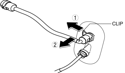
2. Disconnect the reserve hose.
Clutch Pipe Removal Note
CAUTION:
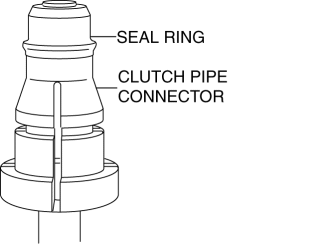
- When disconnecting the clutch pipe, the seal ring installed to the end of the clutch pipe connector may fall off or remain on the clutch pedal component clutch master cylinder side. If the clutch pipe is assembled with the seal ring not installed, it may cause fluid leakage from the clutch pipe connector or the clutch may not operate normally. When disconnecting the clutch pipe, remove the seal ring and clutch pipe connector as a single unit.
NOTE:
- A seal ring has been installed to the mid-connector between the clutch master cylinder and clutch release cylinder. Verify that the clutch pipe is removed together with the seal ring when disconnecting the mid-connector.
- The O-ring type mid-connector seal ring is installed to the groove at the end of the clutch pipe.
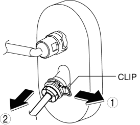
1. Pull the clutch master cylinder clip to the position shown in the figure and pull out the clutch pipe connector straight to detach it.
2. Verify that the seal ring is removed together with the clutch pipe connector.
Starter Interlock Switch Installation Note
1. After installing the clutch pedal component, inspect the clutch pedal. (See CLUTCH PEDAL INSPECTION).
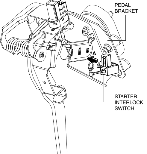
2. Insert the new starter interlock switch into the pedal bracket hole in the direction indicated by arrow A.
3. Slide the starter interlock switch pressing it in the direction indicated by arrow B until it is locked.
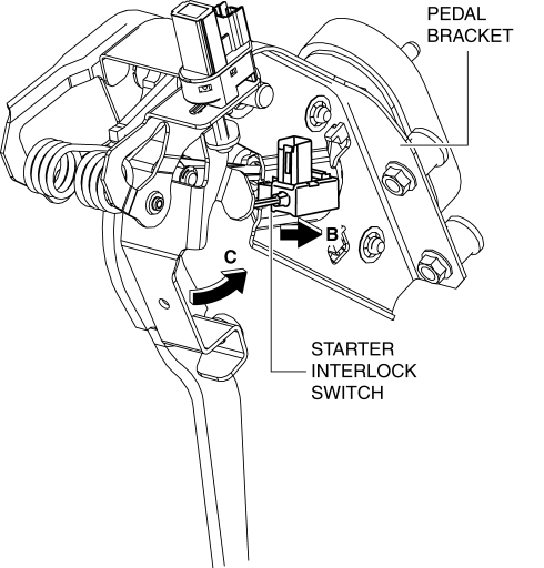
4. Fully depress the clutch pedal in the direction of arrow C, and verify that a click sound from the starter interlock switch is heard.
Clutch Pedal Position Switch Installation Note
1. Insert the new clutch pedal position switch into hole of the pedal bracket until the switch stops.
2. Rotate the clutch pedal position switch 45

