Mazda 2: Solenoid Valve
SOLENOID VALVE INSPECTION
CAUTION:
- Water or foreign objects entering the connector can cause a poor connection or corrosion. Be sure not to drop water or foreign objects on the connector when disconnecting it.
On-Vehicle Inspection
1. Disconnect the coupler component connector.
- Disconnect the negative battery cable.
- Disconnect the coupler component connector.
2. Measure the resistance between the coupler component terminals.
- If there is any malfunction, inspect the coupler component for continuity.
- If coupler component has no malfunction, perform the "Off-Vehicle Inspection". (See Off-Vehicle Inspection).
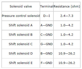
Solenoid valve specification
Operating Inspection
CAUTION:
- Do not apply battery positive voltage to terminals for more than 3 s.
NOTE:
- Because the operation sound of the valves is small, perform inspection in a quiet place.
1. Disconnect the coupler component connector.
- Disconnect the negative battery cable.
- Disconnect the coupler component connector.

2. Apply battery positive voltage to the coupler component terminals A, B, C, F or G and battery negative voltage to GND, and verify that operating sound is heard from solenoid valve.

- If the "click" is not heard, inspect the coupler component.
- If coupler component has no malfunction, perform the "Off-Vehicle Inspection". (See Off-Vehicle Inspection).
3. Apply battery positive voltage to the coupler component terminal D and battery negative voltage to terminal I, and verify that operating sound is heard from solenoid valve.

- If the "click" is not heard, inspect the coupler component.
- If coupler component has no malfunction, perform the "Off-Vehicle Inspection". (See Off-Vehicle Inspection).
Off-Vehicle Inspection
1. Measure the resistance of each solenoid valve individually.
If there is any malfunction, replace the solenoid valve.
Pressure control solenoid specification
- 2.4-7.3 ohms
Shift solenoid A, B, C specification
- 1.0-4.2 ohms
Shift solenoid D, E specification
- 10.9-26.2 ohms
SOLENOID VALVE REMOVAL/INSTALLATION
WARNING:
- A hot transaxle and ATF can cause severe burns. Turn off the engine and wait until they are cool.
- Using compressed air can cause dirt and other particles to fly out, causing injury to the eyes. Wear protective eyeglasses whenever using compressed air.
CAUTION:
- Water or foreign objects entering the connector can cause a poor connection or corrosion. Be sure not to drop water or foreign objects on the connector when disconnecting it.
1. Disconnect the negative battery cable.
2. Clean the transaxle exterior throughout with a steam cleaner or cleaning solvents.
3. Drain the ATF into a separate suitable container. (See AUTOMATIC TRANSAXLE FLUID (ATF) REPLACEMENT).
4. Remove the oil pan. (See CONTROL VALVE BODY REMOVAL/INSTALLATION).
5. Remove the control valve body. (See CONTROL VALVE BODY REMOVAL/INSTALLATION).
6. Install in the reverse order of removal.
7. Add the ATF. (See AUTOMATIC TRANSAXLE FLUID (ATF) REPLACEMENT).
8. Connect the negative battery cable.
9. Perform the "Mechanical System Test". (See MECHANICAL SYSTEM TEST).
10. Perform the "Road Test". (See MECHANICAL SYSTEM TEST).
- Bracket
- Shift solenoid A
- Shift solenoid C
- Shift solenoid B
- Shift solenoid E
- Shift solenoid D
- Pressure control solenoid
- O-ring

