Mazda 2: PCM
PCM INSPECTION
CAUTION:
- Water or foreign objects entering the connector can cause a poor connection or corrosion. Be sure not to drop water or foreign objects on the connector when disconnecting it.
NOTE:
- The PCM terminal voltage can vary with conditions when measuring and changes due to age deterioration on the vehicle, causing false diagnosis. Therefore a comprehensive inspection of the input and output systems, and the PCM is necessary to determine where the malfunction occurs.
1. Remove the PCM connector cover. (See PCM REMOVAL/INSTALLATION).
2. Connect the voltmeter (-) lead to body GND.
3. Measure the voltage at each terminal.
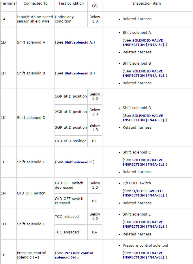
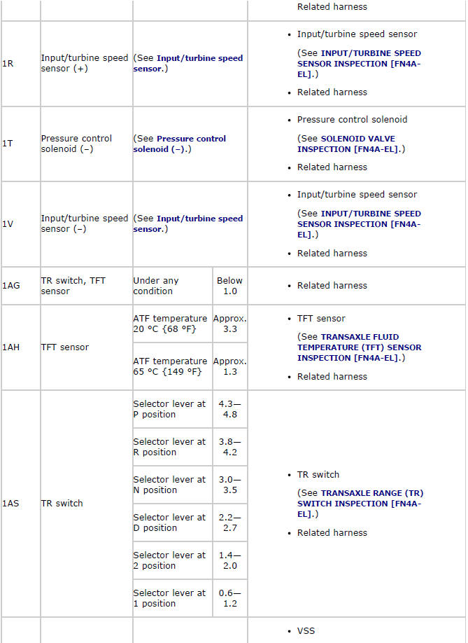
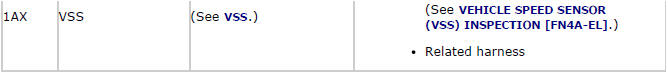
- If any incorrect voltage is detected, inspect the related system(s), wiring harnesses and connector(s) referring to the "Inspection Item" column in the "PCM Terminal Voltage".
PCM Terminal Voltage (Reference)
NOTE:
- Only the transaxle-related information is described.
Input/Output Wave From (Reference)
Shift solenoid A
PCM terminals
- 1D (+)-Negative battery terminal (-)
Oscilloscope setting
- 5 V/DIV (Y), 5 ms/DIV (X), DC range
Vehicle condition
- D position O/D
Shift solenoid B

PCM terminals
- 1H (+)-Negative battery terminal (-)
Oscilloscope setting
- 5 V/DIV (Y), 5 ms/DIV (X), DC range
Vehicle condition
- D position 1GR
Shift solenoid C

PCM terminals
- 1L (+)-Negative battery terminal (-)
Oscilloscope setting
- 5 V/DIV (Y), 5 ms/DIV (X), DC range
Vehicle condition
- D position 1GR
Pressure control solenoid (+)
PCM terminals
- 1P (+)-Negative battery terminal (-)
Oscilloscope setting
- 5 V/DIV (Y), 1 ms/DIV (X), DC range
Vehicle condition
- Idle at P position after warm-up
Pressure control solenoid (-)
PCM terminals
- 1T (+)-Negative battery terminal (-)
Oscilloscope setting
- 5 V/DIV (Y), 1 ms/DIV (X), DC range
Vehicle condition
- Idle at P position after warm-up
Input/turbine speed sensor
PCM terminals
- 1R (+)-1V (-)
Oscilloscope setting
- 1 V/DIV (Y), 2 ms/DIV (X), DC range
Vehicle condition
- Idle at P position after warm-up
VSS
PCM terminals
- 1AX (+)-Negative battery terminal (-)
Oscilloscope setting
- 1 V/DIV (Y), 2 ms/DIV (X), DC range
Vehicle condition
- The following conditions are met:
- Vehicle speed: 30 km/h {19 mph}
- Gear position: 3GR
PCM REMOVAL/INSTALLATION
1. Remove and install the PCM. (See PCM REMOVAL/INSTALLATION).
AUTOMATIC TRANSAXLE REMOVAL/INSTALLATION
CAUTION:
- Secure the steering wheel using tape or a cable to prevent the steering shaft from rotating after disconnecting the steering shaft. If the steering wheel rotates after the steering shaft and the steering gear and linkage are disconnected, the internal parts of the clock spring could be damaged.
1. Disconnect the negative battery cable.
2. Drain the ATF into a separate suitable container. (See AUTOMATIC TRANSAXLE FLUID (ATF) REPLACEMENT).
3. Disconnect and/or remove the following parts.
- Remove the battery, battery tray. (See BATTERY REMOVAL/INSTALLATION).
- Remove the battery tray bracket. (See ENGINE REMOVAL/INSTALLATION).
- Remove the fresh-air duct and air cleaner component as a single unit. (See INTAKE-AIR SYSTEM REMOVAL/INSTALLATION).
- Disconnect the selector cable from the transaxle. (See AUTOMATIC TRANSAXLE SHIFT MECHANISM REMOVAL/INSTALLATION).
- Disconnect the connector and GND wiring harness from the transaxle.
- Remove the EGR pipe installation bolt. (See EGR PIPE REMOVAL/INSTALLATION).
- Remove the bracket from the transaxle.
- Disconnect the oil hose from the transaxle. (See OIL COOLER REMOVAL/INSTALLATION).
- Disconnect the oil hose clip from the No.4 engine mount bracket. (See OIL COOLER REMOVAL/INSTALLATION).
- Remove the water-cooled oil cooler from the transaxle with the hose connected. (See OIL COOLER REMOVAL/INSTALLATION).
- Remove the filler tube from the transaxle.
- Remove the starter. (See STARTER REMOVAL/INSTALLATION).
4. Disconnect and/or remove the following parts.
- Remove the front tires. (See GENERAL PROCEDURES (FRONT AND REAR AXLES) ).
- Disconnect the ABS wheel-speed sensors from the steering knuckles. (See FRONT ABS WHEEL-SPEED SENSOR REMOVAL/INSTALLATION).
- Remove the clip, then unlock the brake pipe. (vehicle left side) (See BRAKE HOSE (FRONT) REMOVAL/INSTALLATION).
- Disconnect the tie-rod end ball joints from the steering knuckles. (See FRONT CROSSMEMBER REMOVAL/INSTALLATION).
- Disconnect the front lower arm ball joint from the steering knuckles. (See FRONT LOWER ARM REMOVAL/INSTALLATION).
- Disconnect the stabilizer control links from the front shock absorbers. (See FRONT SHOCK ABSORBER AND COIL SPRING REMOVAL/INSTALLATION).
- Disconnect the drive shaft from the transaxle. (See DRIVE SHAFT REMOVAL/INSTALLATION).
- Remove the joint shaft. (See JOINT SHAFT REMOVAL/INSTALLATION).
5. Install the SST (49 C017 5A0, 49 UN30 3050) using the following procedure.
CAUTION:
- Refer to the SST instruction manual for the basic handing procedure.
- Set the bracket and vacuum pipe out of the way to prevent interference with the SST as shown in the figure.

CAUTION:
- When attaching the SST in the engine rear side, install a suitable nut between the engine and the SST.
- Using the bolts part number 99794 1025 or M10
READ NEXT:
DRIVE PLATE REMOVAL/INSTALLATION 1. Remove the transaxle. (See AUTOMATIC TRANSAXLE REMOVAL/INSTALLATION). 2. Remove in the order indicated in the table. 3. Install in the reverse order of removal. Drive Plate
OIL SEAL REPLACEMENT CAUTION: The oil seal is easily damaged by the sharp edges of the drive shaft splines. Do not let the splines contact the oil seal. 1. Drain the ATF into a separate suitable Oil Seal
CONTROL VALVE BODY REMOVAL/INSTALLATION On-Vehicle Removal WARNING: Using compressed air can cause dirt and other particles to fly out, causing injury to the eyes. Wear protective eyeglasses when Control Valve Body
