Mazda 2: Control Valve Body
CONTROL VALVE BODY REMOVAL/INSTALLATION
On-Vehicle Removal
WARNING:
- Using compressed air can cause dirt and other particles to fly out, causing injury to the eyes. Wear protective eyeglasses whenever using compressed air.
- A hot transaxle and ATF can cause severe burns. Turn off the engine and wait until they are cool.
CAUTION:
- Water or foreign objects entering the connector can cause a poor connection or corrosion. Be sure not to drop water or foreign objects on the connector when disconnecting it.
1. Disconnect the negative battery cable.
2. Clean the transaxle exterior throughout with a steam cleaner or cleaning solvents.
3. Drain the ATF into a separate suitable container. (See AUTOMATIC TRANSAXLE FLUID (ATF) REPLACEMENT).
4. Remove the oil pan.
5. Disconnect each solenoid valve connector.

6. Remove the TFT sensor and GND.
7. Remove the oil strainer.
8. Remove the bolts as shown, then remove the control valve body.
9. Remove the accumulators and accumulator springs.
On-Vehicle Installation
CAUTION:
- Be sure to align the parking rod and the manual valve.
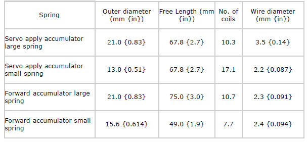
1. Install the accumulator springs, accumulators and control valve body.
Accumulator spring specification
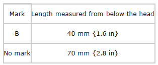
2. Tighten the bolts as shown to install the control valve body.
Tightening torque
- 8-10 N*m {82-101 kgf*cm, 71-88 in*lbf}
Bolt length measured from below the head
3. Install the oil strainer.
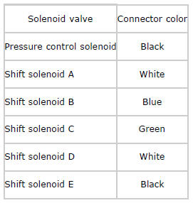
4. Match the harness colors, then connect each solenoid valves connector. Connector color (harness-side)
5. Install the GND.
Tightening torque
- 8-10 N*m {82-101 kgf*cm, 71-88 in*lbf}
6. Install the TFT sensor to the oil strainer.
CAUTION:
- If any sealant remains on the sealing surfaces of the transaxle case and oil pan, transaxle damage may occur. Use a cleaning fluid to remove any old sealant from the transaxle case and oil pan.
7. Apply a light coat of sealant (TB1217E or equivalent) to the contact surfaces of the oil pan and transaxle case.
8. Install the oil pan before the applied sealant starts to harden.
CAUTION:
- The removed bolts with spring washer cannot be reused. If they are reused, it could loosen the bolts due to spring weakness.
Tightening torque
- Flange bolt: 6.0-8.0 N*m {62-81 kgf*cm, 54-70 in*lbf}
- Bolt with spring washer: 8-10 N*m {82-101 kgf*cm, 71-88 in*lbf}
9. Add the ATF. (See AUTOMATIC TRANSAXLE FLUID (ATF) REPLACEMENT).
10. Connect the negative battery cable.
11. Perform the "Mechanical System Test". (See MECHANICAL SYSTEM TEST).
12. Perform the "Road Test". (See ROAD TEST).

