Mazda 2: Electric Power Steering (EPS)
ELECTRIC POWER STEERING (EPS) SYSTEM WIRING DIAGRAM
ELECTRIC POWER STEERING (EPS) ON-BOARD DIAGNOSIS
On-Board Diagnostic (OBD) Test Description
- The OBD test inspects the integrity and function of the EPS and outputs the results when requested by the specific tests.
- On-board diagnostic test also:
- Provides a quick inspection of the EPS usually performed at the start of each diagnostic procedure.
- Provides verification after repairs to ensure that no other faults occurred during service.
- The OBD test is divided into 2 tests:
- Read/clear diagnostic results, PID/Data monitor and record.
Read/clear diagnostic results
- This function allows reading or clearing of DTCs in the EPS CM memory.
PID/Data monitor and record
- This function allows access of certain data values, input signals, calculated values, and system status information.
Reading DTCs Procedure
1. Connect the M-MDS (IDS) to the DLC-2.
2. After the vehicle is identified, select the following items from the initialization screen of the IDS.
- Select "Self Test".
- Select "Modules".
- Select "EPS".
3. Verify the DTC according to the directions on the screen.
- If any DTCs are displayed, perform troubleshooting according to the corresponding DTC inspection.
4. After completion of repairs, clear all DTCs stored in the EPS CM. (See Clearing DTCs Procedures).
Clearing DTCs Procedures
1. Connect the M-MDS (IDS) to the DLC-2.
2. After the vehicle is identified, select the following items from the initialization screen of the IDS.
- Select "Self Test".
- Select "Modules".
- Select "EPS".
3. Verify the DTC according to the directions on the screen.
4. Press the clear button on the DTC screen to clear the DTC.
5. Switch the ignition to off.
6. Switch the ignition to ON and wait for 5 s or more.
7. Perform DTC inspection. (See Reading DTCs Procedure).
8. Verify that no DTCs are displayed.
PID/Data Monitor and Record Procedure
1. Connect the M-MDS (IDS) to the DLC-2.
2. After the vehicle is identified, select the following items from the initialization screen of the IDS.
- Select "DataLogger".
- Select "Modules".
- Select "EPS".
3. Select the applicable PID from the PID table.
4. Verify the PID data according to the directions on the screen.
NOTE:
- The PID data screen function is used for monitoring the calculated value of input/output signals in the module. Therefore, if the monitored value of the output parts is not within the specification, it is necessary to inspect the monitored value of input parts corresponding to the applicable output part control. In addition, because the system does not display an output part malfunction as an abnormality in the monitored value, it is necessary to inspect the output parts individually.
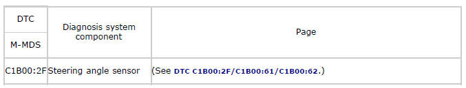
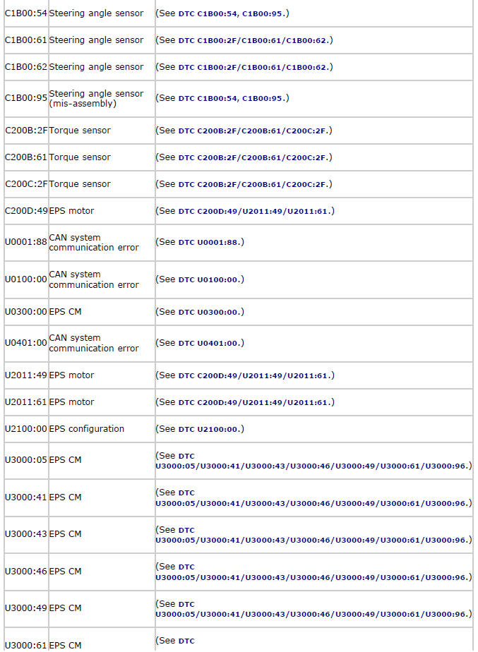
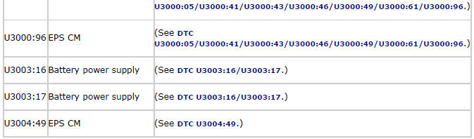
DTC Table
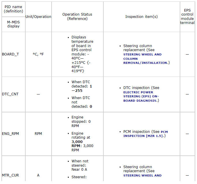
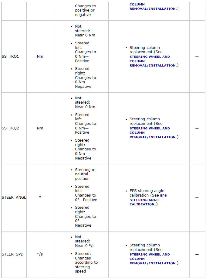
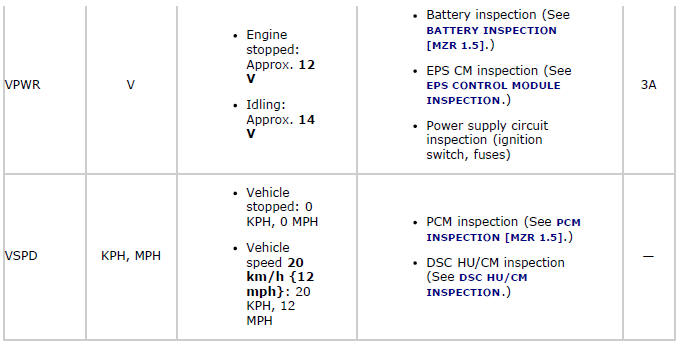
PID/DATA Monitor Table
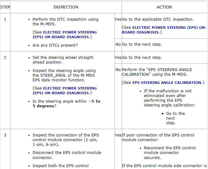
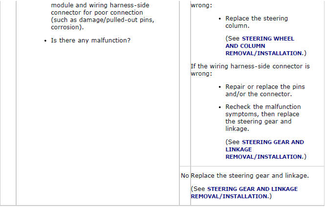
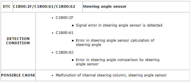
DTC C1B00:2F/C1B00:61/C1B00:62
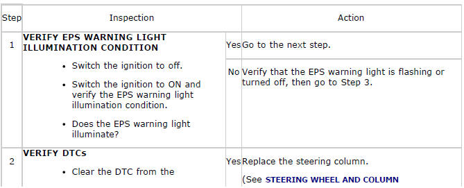
Diagnostic Procedure

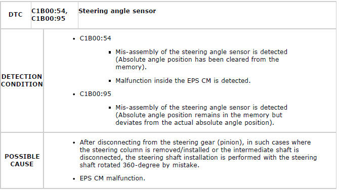
DTC C1B00:54, C1B00:95
Diagnostic Procedure
DTC C200B:2F/C200B:61/C200C:2F
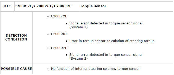
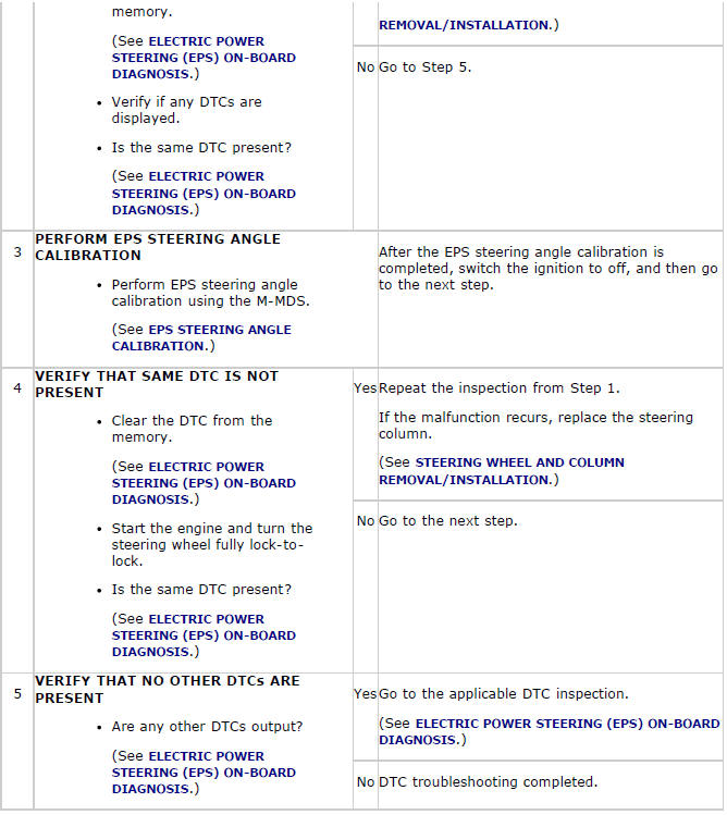
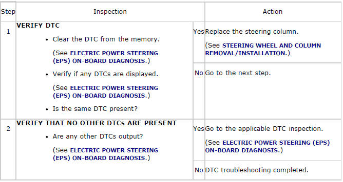
Diagnostic Procedure
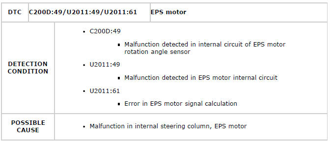
DTC C200D:49/U2011:49/U2011:61
Diagnostic Procedure
DTC U0001:88
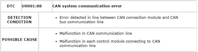
Diagnostic Procedure
- Perform inspection according to the diagnostic procedure in BODY &
ACCESSORIES.
(See FOREWORD [MULTIPLEX COMMUNICATION SYSTEM] ).
DTC U0100:00
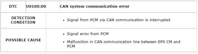
Diagnostic Procedure
- Perform inspection according to the diagnostic procedure in BODY &
ACCESSORIES.
(See FOREWORD [MULTIPLEX COMMUNICATION SYSTEM] ).
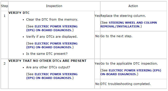
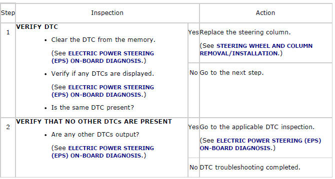
DTC U0300:00
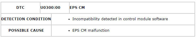
Diagnostic Procedure
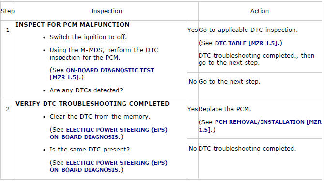
DTC U0401:00
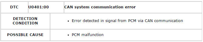
Diagnostic Procedure
DTC U2100:00
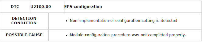
Diagnostic Procedure
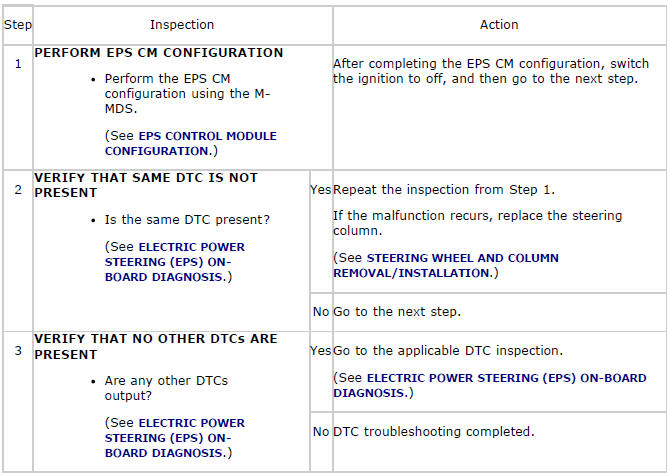
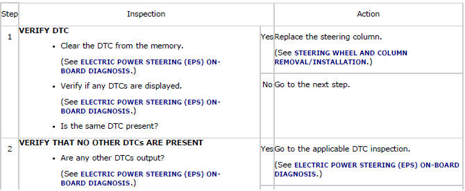
DTC U3000:05/U3000:41/U3000:43/U3000:46/U3000:49/U3000:61/U3000:96
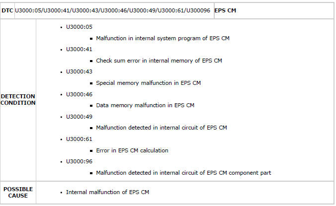
Diagnostic Procedure

DTC U3003:16/U3003:17
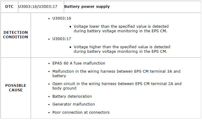
System wiring diagram
Diagnostic Procedure
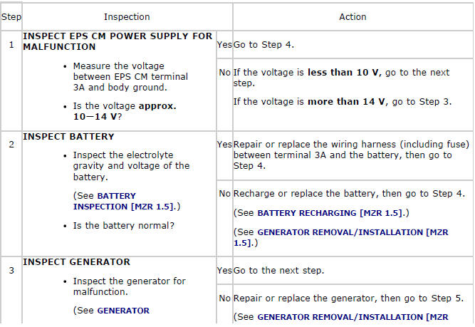
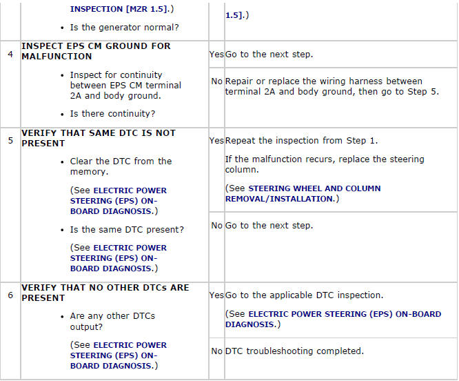
DTC U3004:49
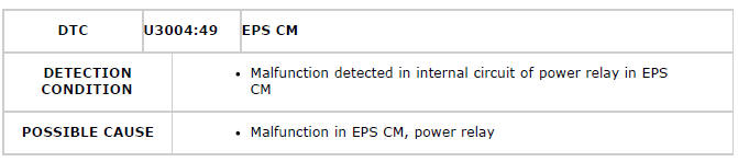
Diagnostic Procedure

ELECTRIC POWER STEERING (EPS) SYSTEM WIRING DIAGRAM
FOREWORD
- Before performing the steps in Symptom Troubleshooting, perform the On-board Diagnostic Inspection. To inspect the DTC, follow the DTC Inspection steps. (See ELECTRIC POWER STEERING (EPS) ON-BOARD DIAGNOSIS).
PRECAUTION
Intermittent Concern Troubleshooting
Vibration method
- If a malfunction occurs or becomes worse while driving on a rough road or when the engine is vibrating, perform the following steps.
NOTE:
- There are several reasons why vehicle or engine vibration could cause an
electrical
malfunction. Inspect the following:
- Connectors not fully seated.
- Wiring harnesses not having full play.
- Wires laying across brackets or moving parts.
- Wires routed too close to hot parts.
- An improperly routed, improperly clamped, or loose wiring harness can cause wiring to become pinched between parts.
- The connector joints, points of vibration, and places where wiring harness pass through the firewall, body panels and other panels are the major areas to be inspected.
Inspection method for switch and/or sensor connectors or wires
1. Connect the M-MDS to the DLC-2.
2. Switch the ignition to ON (engine off).
NOTE:
- If the engine starts and runs, perform the following steps at idle.
3. Access PIDs for the switch you are inspecting.
4. Turn the switch on manually.
5. Slightly shake each connector or wiring harness vertically and horizontally while monitoring the PID.
- If the PID value is unstable, inspect for poor connection.
Inspection method for sensors
1. Connect the M-MDS to the DLC-2.
2. Switch the ignition to ON (engine off).
NOTE:
- If the engine starts and runs, perform the following steps at idle.
3. Access PIDs for the switch you are inspecting.
4. Vibrate the sensor slightly with your finger.
- If the PID value is unstable or a malfunction occurs, inspect for poor connection and/or poorly mounted sensor.
Connector terminal inspection method
1. Inspect the connection of each female terminal.
2. Insert the male terminal to the female terminal and inspect the female terminal for looseness.
SYMPTOM TROUBLESHOOTING
- Verify the symptom, and perform troubleshooting according to the appropriate number.
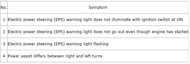
NO.1 ELECTRIC POWER STEERING (EPS) WARNING LIGHT DOES NOT ILLUMINATE WITH IGNITION SWITCH AT ON
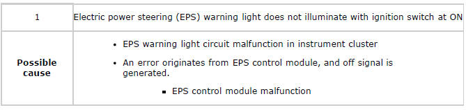
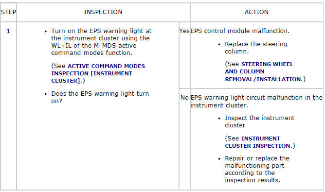
Diagnostic procedure
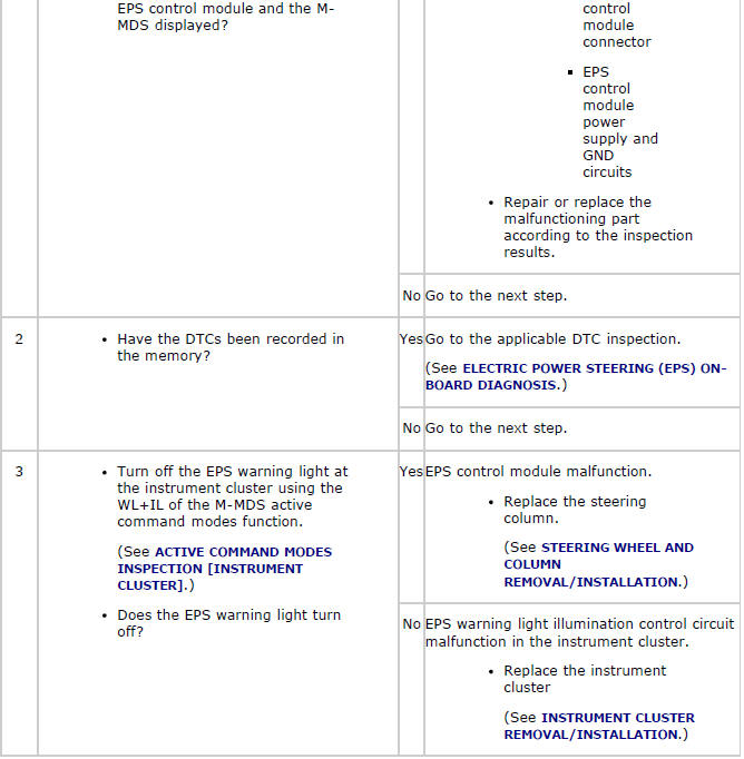
NO.2 ELECTRIC POWER STEERING (EPS) WARNING LIGHT DOES NOT GO OUT EVEN THOUGH ENGINE HAS STARTED
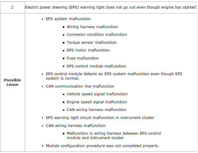
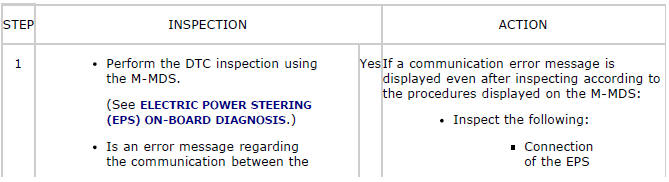
Diagnostic procedure
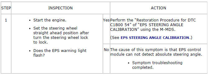
NO.3 ELECTRIC POWER STEERING (EPS) WARNING LIGHT FLASHING
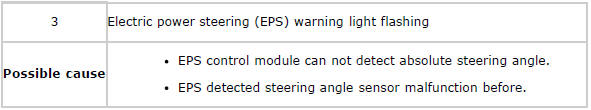
Diagnostic procedure
NO.4 POWER ASSIST DIFFERS BETWEEN RIGHT AND LEFT TURNS
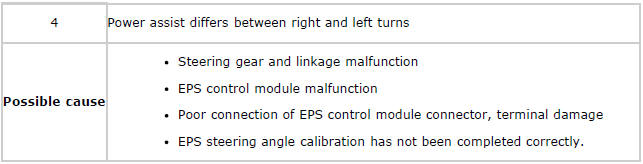
Diagnostic procedure