Mazda 2: Oil Seal
OIL SEAL REPLACEMENT
CAUTION:
- The oil seal is easily damaged by the sharp edges of the drive shaft splines. Do not let the splines contact the oil seal.
1. Drain the ATF into a separate suitable container. (See AUTOMATIC TRANSAXLE FLUID (ATF) REPLACEMENT).
2. Remove the drive shaft and/or joint shaft. (See DRIVE SHAFT REMOVAL/INSTALLATION).
(See JOINT SHAFT REMOVAL/INSTALLATION).
3. Remove the oil seal using the flathead screwdriver.
4. Using the SSTs and a hammer, tap a new oil seal in evenly until the SSTs contacts the transaxle case.
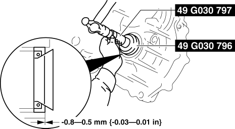
5. Coat the lip of the oil seal with ATF.
6. Install the drive shaft and/or joint shaft. (See DRIVE SHAFT REMOVAL/INSTALLATION).
(See JOINT SHAFT REMOVAL/INSTALLATION).
7. Add the ATF. (See AUTOMATIC TRANSAXLE FLUID (ATF) REPLACEMENT).
8. Perform the "Mechanical System Test". (See MECHANICAL SYSTEM TEST).
OIL COOLER REMOVAL/INSTALLATION
WARNING:
- A hot transaxle and ATF can cause severe burns. Turn off the engine and wait until they are cool.
- Using compressed air can cause dirt and other particles to fly out, causing injury to the eyes. Wear protective eyeglasses whenever using compressed air.
NOTE:
- After removing the oil cooler, check for dirt or foreign objects mixed into the ATF and flush the oil cooler if necessary.
1. Disconnect the negative battery cable.
2. Drain the ATF into a separate suitable container. (See AUTOMATIC TRANSAXLE FLUID (ATF) REPLACEMENT [FN4AEL] ).
3. Remove in the order indicated in the table.
4. Install in the reverse order of removal.
5. Add the ATF. (See AUTOMATIC TRANSAXLE FLUID (ATF) REPLACEMENT).
6. Connect the negative battery cable.
7. Perform the "Line Pressure Test". (See MECHANICAL SYSTEM TEST).
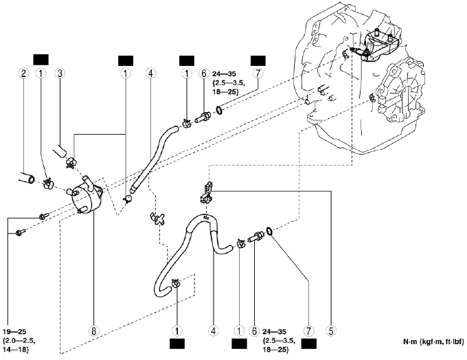
- Hose clamp
- Water hose (connected to the water pipe)
- Water hose (connected to the outlet)
- Oil hose
- Oil hose clip
- Connector bolt
- Packing
- Water-cooled oil cooler
Oil Hose Installation Note
1. Install the oil hose.
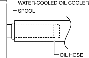
Water-cooled oil cooler side
- Install the oil hose into the water-cooled oil cooler to the position shown in the figure.
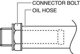
Connector bolt side
- Install the oil hose into the connector bolt to the position shown in the figure.
2. Install the hose clamp within the marked area of the oil hose.
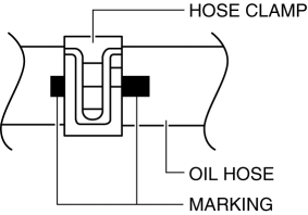
NOTE:
- If the oil hose is to be re-used, install the hose clamp to the impression in the hose left by the previous installation. After installation, apply force to the hose clamp in the direction of the arrows to engage the hose clamp securely.
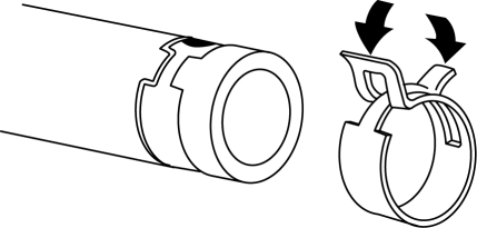
3. Verify that the hose clamp does not interfere with any other components.
OIL COOLER FLUSHING
WARNING:
- A hot transaxle and ATF can cause severe burns. Turn off the engine and wait until they are cool before changing the ATF.
- Using compressed air can cause dirt and other particles to fly out, causing injury to the eyes. Wear protective eyeglasses whenever using compressed air.
NOTE:
- If the transaxle is replaced, flush and inspect the oil cooler.
- When replacing the transaxle, inspect the oil cooler together with flushing it using the following procedures, and with the oil hose removed.
1. Disconnect the oil cooler hose from the transaxle. (See OIL COOLER REMOVAL/INSTALLATION).
2. Set a clean oil pan up to the oil cooler hose inlet
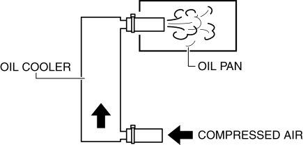
3. Blow 491-882 kPa {5.01-8.99 kgf/cm2, 71.3-127.0 psi} of compressed air into the oil cooler hose outlet to drain remaining oil.
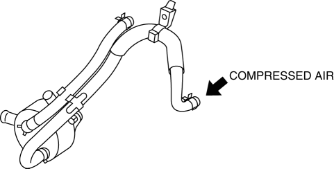
4. Add new ATF from the oil cooler hose outlet and blow 491-882 kPa {5.01-8.99 kgf/cm2, 71.3-127.0 psi} of compressed air to flush. (Repeat 2 or 3 times)
5. Verify that none of the following foreign material is mixed in with the drained ATF:
- Large metal fragments of φ 0.5 mm {0.02 in} or more that cannot pass through the oil strainer
- Fibrous clutch facing
6. Repeat the procedures from Step 4 and flush the inside of the oil cooler.
- If foreign material such as metal fragments or clutch facing remains even after the oil cooler is flushed repeatedly, replace the oil cooler. (See OIL COOLER REMOVAL/INSTALLATION).

