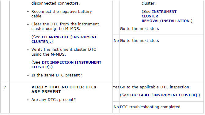
Mazda 2: DTC Table [Instrument Cluster]
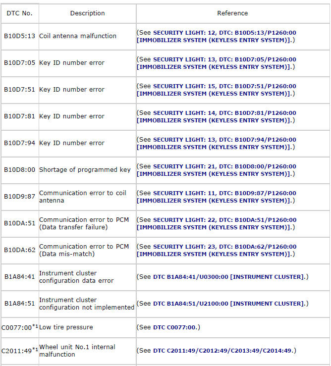
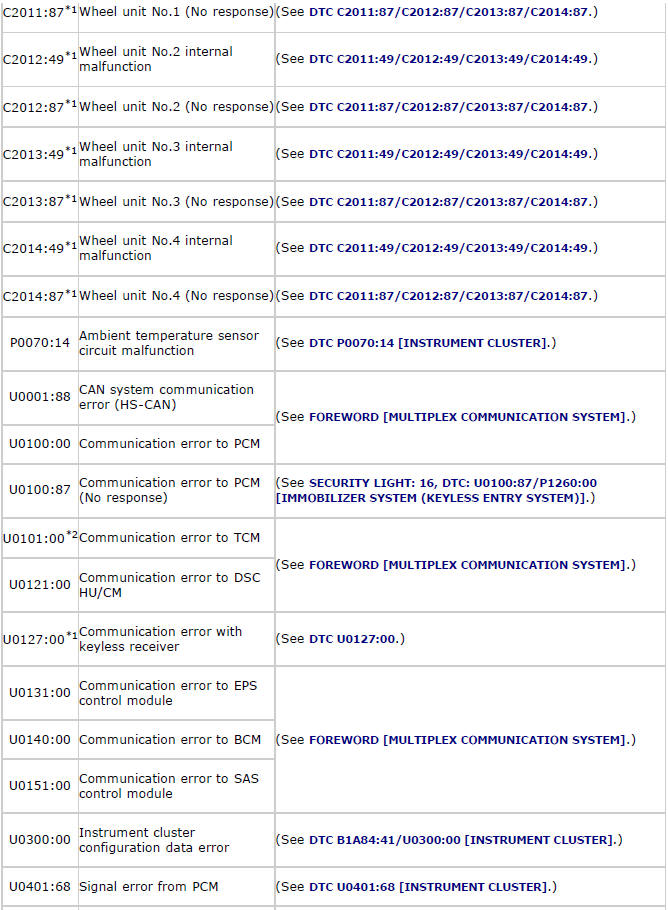
*1 Vehicles with tire pressure monitoring system
*2 ATX
DTC B1A84:41/U0300:00
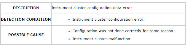
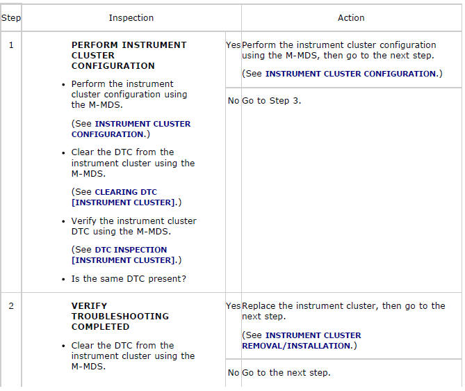
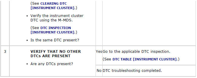
Diagnostic Procedure
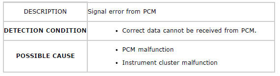
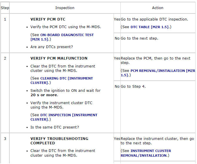
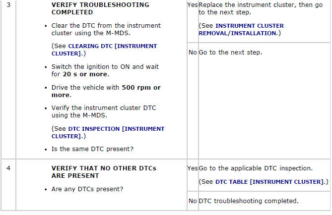
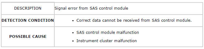
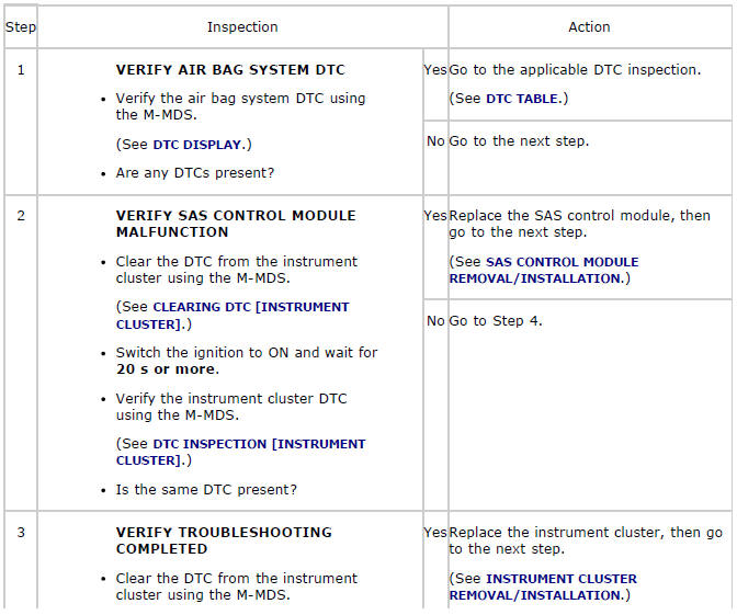
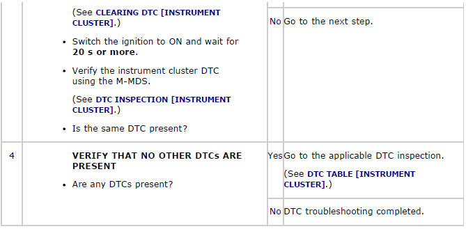
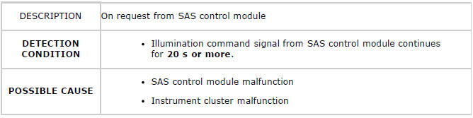
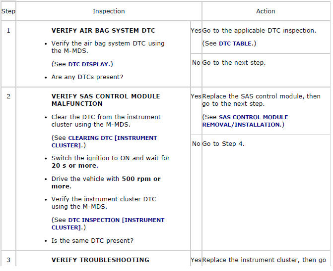
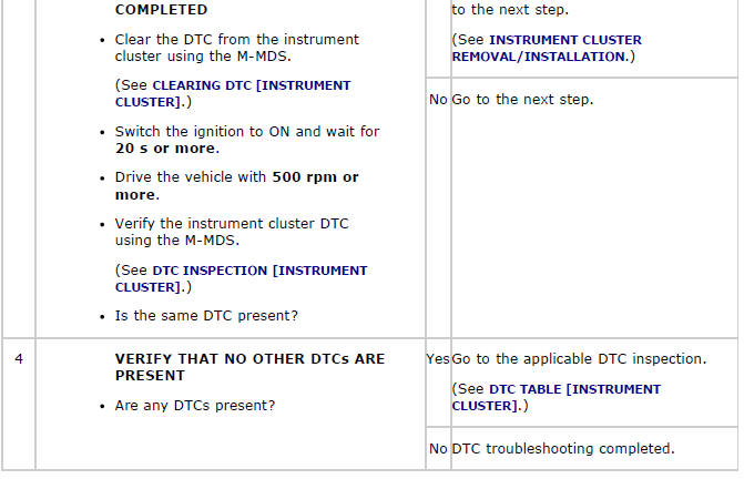
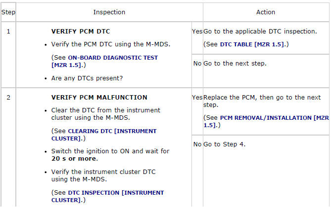
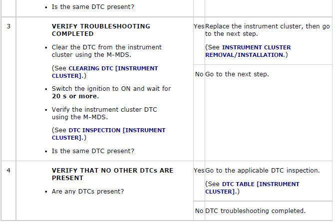
DTC B1A84:51/U2100:00
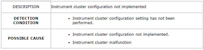
Diagnostic Procedure
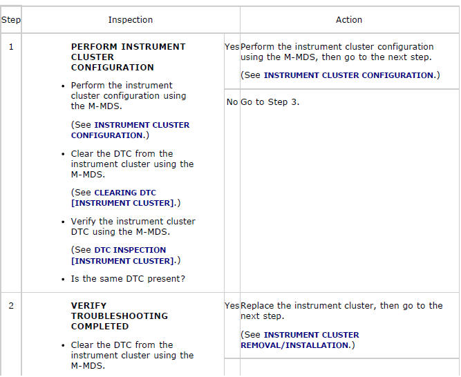
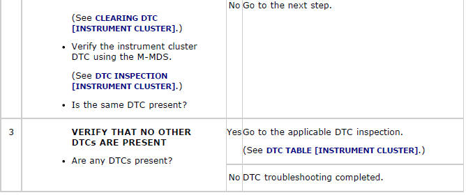
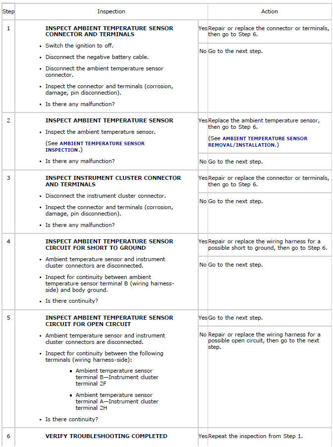
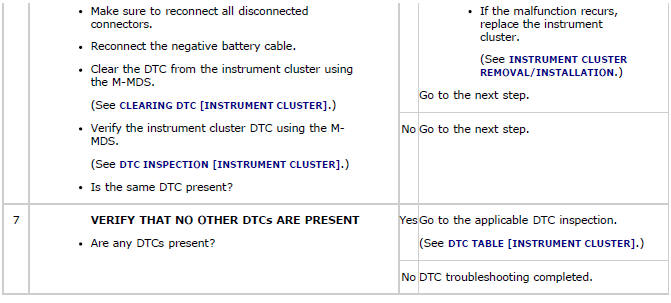
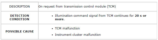
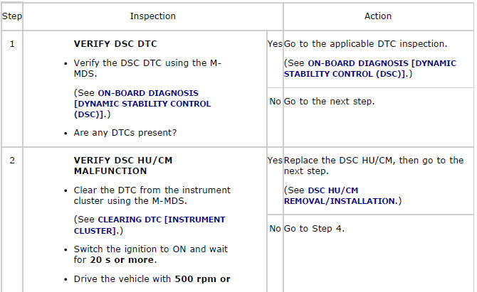
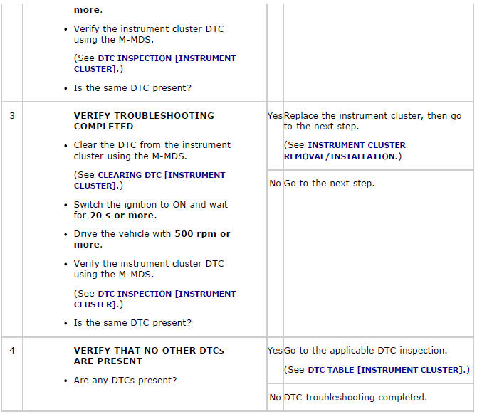
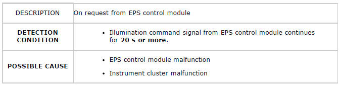
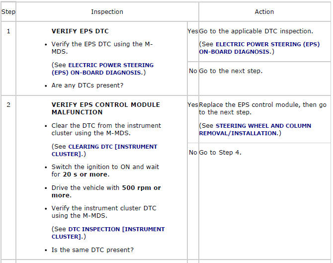
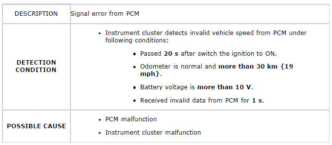
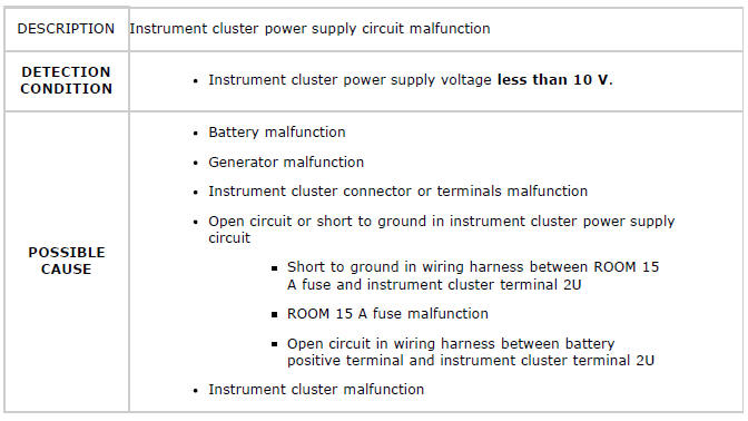
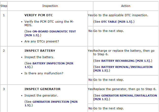
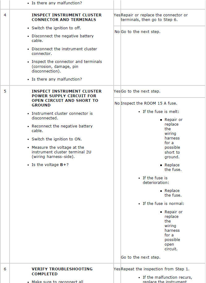
DTC P0070:14
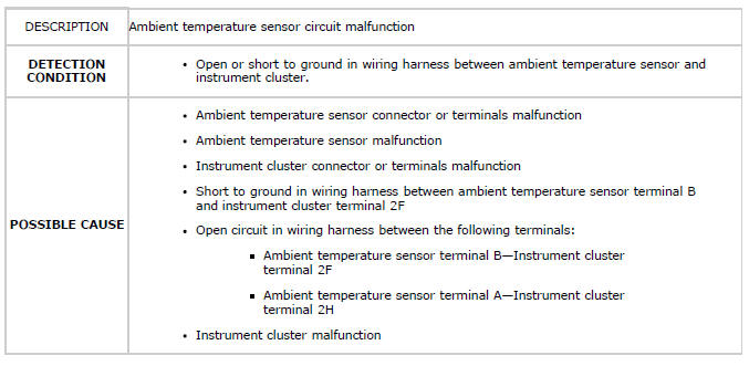
System Wiring Diagram
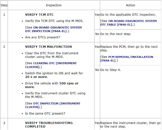
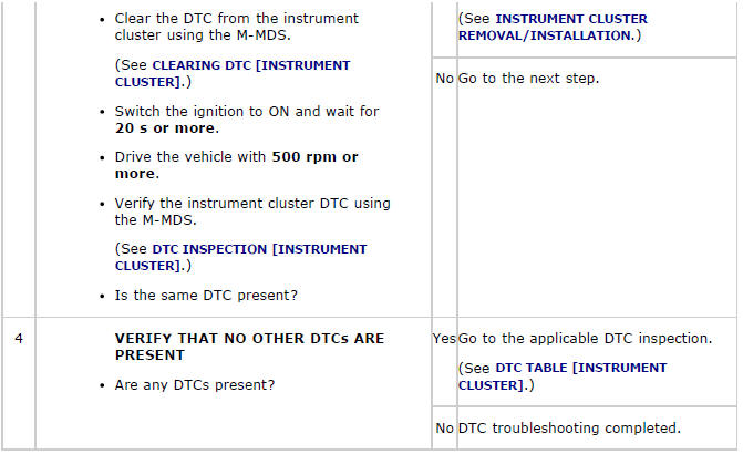
Diagnostic Procedure
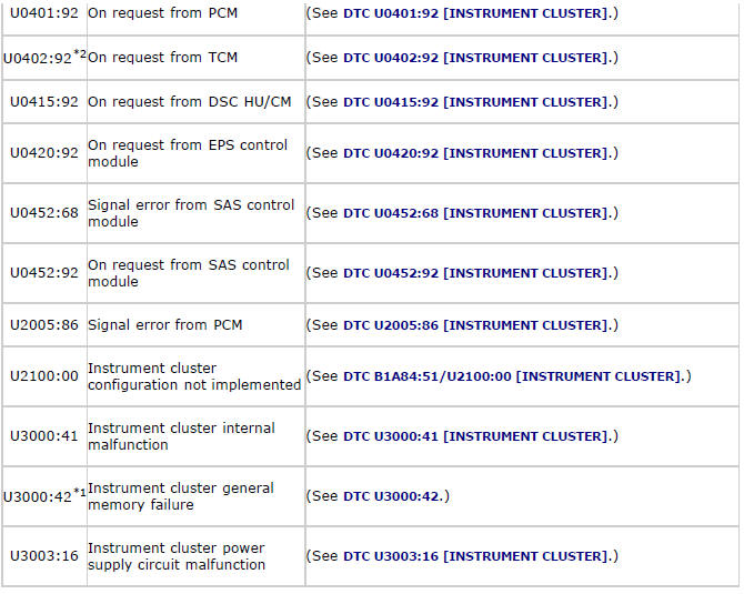
DTC U0401:68
Diagnostic Procedure
DTC U0401:92
Diagnostic Procedure
DTC U0402:92
Diagnostic Procedure
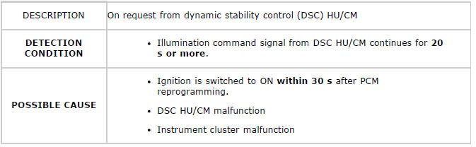
DTC U0415:92
NOTE:
- If the ignition is switched to off after reprogramming the PCM and then switched to ON within 30 s, the PCM reprogramming cannot be completed correctly and DTC U0415:92 is stored.
Diagnostic Procedure
DTC U0420:92
Diagnostic Procedure
DTC U0452:68
Diagnostic Procedure
DTC U0452:92
Diagnostic Procedure
DTC U2005:86
Diagnostic Procedure
DTC U3000:41
Diagnostic Procedure
DTC U3003:16
System Wiring Diagram
Diagnostic Procedure
PID/DATA MONITOR INSPECTION [Instrument Cluster]
1. Connect the M-MDS (IDS) to the DLC-2.
2. After the vehicle is identified, select the following items from the initialization screen of the IDS.
- Select "DataLogger".
- Select "Modules".
- Select "IC".
3. Select the applicable PID from the PID table.
4. Verify the PID data according to the directions on the screen.
NOTE:
- The PID data screen function is used for monitoring the calculated value of input/output signals in the module. Therefore, if the monitored value of the output parts is not within the specification, it is necessary to inspect the monitored value of input parts corresponding to the applicable output part control. In addition, because the system does not display an output part malfunction as an abnormality in the monitored value, it is necessary to inspect the output parts individually.
PID/DATA MONITOR TABLE [Instrument Cluster]
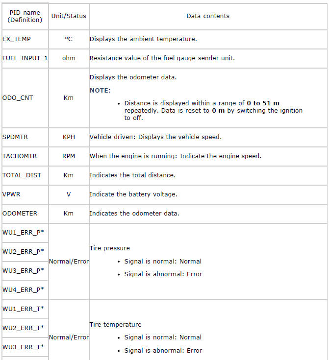
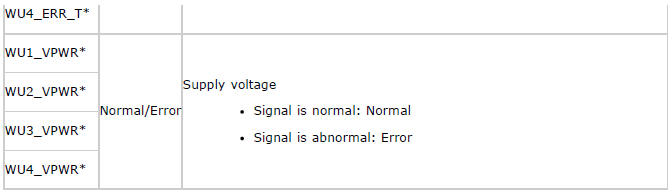
* Vehicles with tire pressure monitoring system
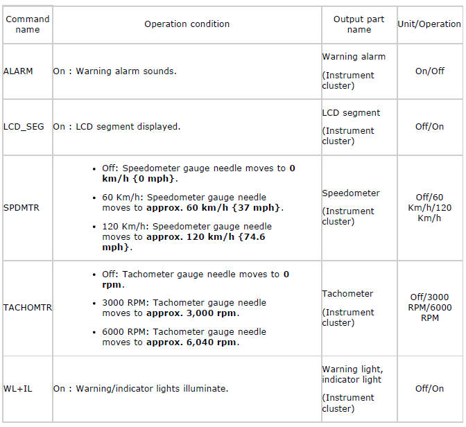
ACTIVE COMMAND MODES INSPECTION [Instrument Cluster]
1. Connect the M-MDS (IDS) to the DLC-2.
2. After the vehicle is identified, select the following items from the initialization screen of the IDS.
- Select "DataLogger".
- Select "Modules".
- Select "IC".
3. Select the simulation items from the PID table.
4. Perform the active command modes function, inspect the operations for each parts.
If the operation of output parts cannot be verified after the active command mode inspection is performed, this could indicate the possibility of an open or short circuit, sticking, or operation malfunction in the output parts.
ACTIVE COMMAND MODES TABLE [Instrument Cluster]