Mazda 2: Airflow Mode Link Set
AIRFLOW MODE LINK SET REMOVAL/INSTALLATION
1. Disconnect the negative battery cable.
2. Remove the following parts:
- Rear console (See REAR CONSOLE REMOVAL/INSTALLATION).
- Shift lever knob (MTX) (See MANUAL TRANSAXLE SHIFT MECHANISM REMOVAL/INSTALLATION).
- Side wall (See SIDE WALL REMOVAL/INSTALLATION).
- Front console component (See FRONT CONSOLE COMPONENT REMOVAL/INSTALLATION).
- Front scuff plate (LH) (See FRONT SCUFF PLATE REMOVAL/INSTALLATION).
- Front side trim (LH) (See FRONT SIDE TRIM REMOVAL/INSTALLATION).
- Hood release lever (See HOOD LATCH AND RELEASE LEVER REMOVAL/INSTALLATION).
- Lower panel (driver-side) (See LOWER PANEL REMOVAL/INSTALLATION).
- Knee bolster (See KNEE BOLSTER REMOVAL/INSTALLATION).
- Heat duct (LH) (See HEAT DUCT COMPONENT REMOVAL/INSTALLATION).
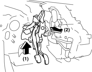
3. Remove the wiring harness clip from the brake pedal.
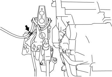
4. Remove the brake pedal installation nuts.
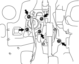
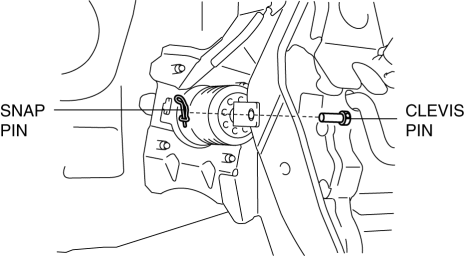
5. Remove the snap pin and clevis pin.
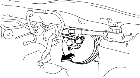
6. Pull the power brake unit from the engine compartment side.
7. Pull the brake pedal outward while lifting it.
CAUTION:
- Apply only the specified grease to links and cranks. Otherwise abnormal noise or improper operation may result.
8. Remove in the order indicated in the table.
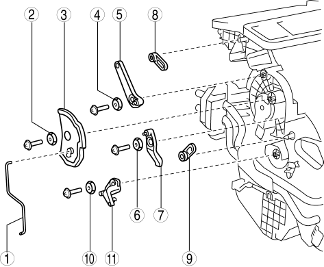
- Airflow mode rod
- Link collar (1)
- Airflow mode main link
- Link collar (2)
- Airflow mode sub link (1)
- Link collar (3)
- Airflow mode sub link (2)
- Airflow mode crank (1)
- Airflow mode crank (2)
- Link collar (4) (manual air conditioner)
- Airflow mode sub link (3) (manual air conditioner)
9. Install in the reverse order of removal.
AIR MIX LINK SET REMOVAL/INSTALLATION
1. Disconnect the negative battery cable.
2. Remove the following parts:
- Glove compartment (See GLOVE COMPARTMENT REMOVAL/INSTALLATION).
- Dashboard under cover (See DASHBOARD UNDER COVER REMOVAL/INSTALLATION).
- Heat duct (RH) (See HEAT DUCT COMPONENT REMOVAL/INSTALLATION).
- Rear console (See REAR CONSOLE REMOVAL/INSTALLATION).
- Shift lever knob (MTX) (See MANUAL TRANSAXLE SHIFT MECHANISM REMOVAL/INSTALLATION).
- Side wall (See SIDE WALL REMOVAL/INSTALLATION).
- Front console component (See FRONT CONSOLE COMPONENT REMOVAL/INSTALLATION).
3. Disconnect the air mix wire.
CAUTION:
- Apply only the specified grease to links and cranks. Otherwise abnormal noise or improper operation may result.
4. Remove in the order indicated in the table.
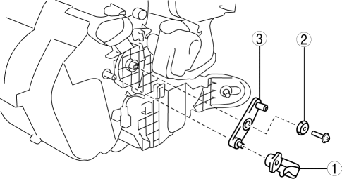
- Air mix crank
- Link collar (5)
- Air mix link
5. Install in the reverse order of removal.
AIR INTAKE LINK SET REMOVAL/INSTALLATION
1. Disconnect the negative battery cable.
2. Remove the following parts:
- Glove compartment (See GLOVE COMPARTMENT REMOVAL/INSTALLATION).
- Dashboard under cover (See DASHBOARD UNDER COVER REMOVAL/INSTALLATION).
- Heat duct (RH) (See HEAT DUCT COMPONENT REMOVAL/INSTALLATION).
- Rear console (See REAR CONSOLE REMOVAL/INSTALLATION).
- Shift lever knob (MTX) (See MANUAL TRANSAXLE SHIFT MECHANISM REMOVAL/INSTALLATION).
- Boot panel (See FRONT CONSOLE COMPONENT DISASSEMBLY/ASSEMBLY).
- Side wall (See SIDE WALL REMOVAL/INSTALLATION).
- Front console component (See FRONT CONSOLE COMPONENT REMOVAL/INSTALLATION).
- Front scuff plate (See FRONT SCUFF PLATE REMOVAL/INSTALLATION).
- Front side trim (See FRONT SIDE TRIM REMOVAL/INSTALLATION).
- Hood release lever (See HOOD LATCH AND RELEASE LEVER REMOVAL/INSTALLATION).
- Lower panel (driver-side) (See LOWER PANEL REMOVAL/INSTALLATION).
- Driver-side air bag module (See DRIVER-SIDE AIR BAG MODULE REMOVAL/INSTALLATION).
- Knee bolster (See KNEE BOLSTER REMOVAL/INSTALLATION).
- Steering wheel (See STEERING WHEEL AND COLUMN REMOVAL/INSTALLATION).
- Column cover (See COLUMN COVER REMOVAL/INSTALLATION).
- Meter hood (See METER HOOD REMOVAL/INSTALLATION).
- Instrument cluster (See INSTRUMENT CLUSTER REMOVAL/INSTALLATION).
- Combination switch (See COMBINATION SWITCH REMOVAL/INSTALLATION).
- Center panel unit (See CENTER PANEL UNIT REMOVAL/INSTALLATION).
- Climate control unit (See CLIMATE CONTROL UNIT REMOVAL/INSTALLATION [MANUAL AIR CONDITIONER] ).
- Shift lever component (MTX) (See MANUAL TRANSAXLE SHIFT MECHANISM REMOVAL/INSTALLATION).
- Selector lever component (ATX) (See AUTOMATIC TRANSAXLE SHIFT MECHANISM REMOVAL/INSTALLATION
- Interlock unit (ATX) (See AUTOMATIC TRANSAXLE SHIFT MECHANISM REMOVAL/INSTALLATION).
- Lower panel (passenger-side) (See LOWER PANEL REMOVAL/INSTALLATION).
- Side panel (See SIDE PANEL REMOVAL/INSTALLATION).
- A-pillar trim (See A-PILLAR TRIM REMOVAL/INSTALLATION).
- Windshield wiper arm and blade (See WINDSHIELD WIPER ARM AND BLADE REMOVAL/INSTALLATION).
- Cowl grille (See COWL GRILLE REMOVAL/INSTALLATION).
- Windshield wiper motor (See WINDSHIELD WIPER MOTOR REMOVAL/INSTALLATION).
- Sail garnish (See SAIL GARNISH REMOVAL/INSTALLATION).
- Steering shaft cover (See STEERING WHEEL AND COLUMN REMOVAL/INSTALLATION).
- Steering shaft (See STEERING WHEEL AND COLUMN REMOVAL/INSTALLATION).
3. Disconnect the dashboard wiring harness connector.
4. Disconnect the antenna feeder No.1 jack.
5. Remove the dashboard. (See DASHBOARD REMOVAL/INSTALLATION).
6. Disconnect the air intake wire. (See CLIMATE CONTROL UNIT REMOVAL/INSTALLATION [MANUAL AIR CONDITIONER] ).
CAUTION:
- Apply only the specified grease to links and cranks. Otherwise abnormal noise or improper operation may result.
7. Remove in the order indicated in the table.
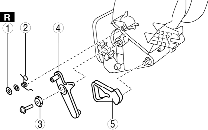
- Bushing nut
- Spring
- Link collar
- Air intake link
- Air intake crank
8. Install in the reverse order of removal.

