Mazda 2: A/C Compressor
A/C COMPRESSOR REMOVAL/INSTALLATION
1. Disconnect the negative battery cable.
2. Remove the splash shield (RH).
3. Collect the refrigerant. (See REFRIGERANT CHARGING).
4. Remove the drive belt. (See DRIVE BELT REMOVAL/INSTALLATION] ).
5. Remove the clip retaining the compressor wiring harness to the cooler hose (HI).
CAUTION:
- If moisture or foreign material enters the refrigeration cycle, cooling ability will be lowered and abnormal noise or other malfunction could occur. Always plug open fittings immediately after removing any refrigeration cycle parts.
6. Remove in the order indicated in the table. Do not allow remaining compressor oil in the A/C compressor and pipes to spill.
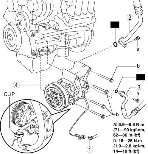
- Connector
- Cooler hose (LO)
- Cooler hose (HI)
- A/C compressor
7. Install in the reverse order of removal.
8. Perform the refrigerant system performance test. (See REFRIGERANT SYSTEM PERFORMANCE TEST).
A/C Compressor Installation Note
CAUTION:
- Due to the high moisture-absorption efficiency of the compressor oil, it may absorb moisture if it is left over a long period of time thereby negatively affecting A/C operation. Drain the compressor oil and refill within 10 min.
1. Drain the oil into a clean container while rotating the shaft of the new A/C compressor 6-8 times. This drained oil is to be re-added to the compressor so be careful not to let it become dirty.
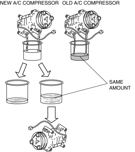
2. For the old compressor, drain the oil into a separate, clean container while rotating the shaft 6-8 times.
3. Compare the quantities of the two oils. The oil quantity from the new A/C compressor should be more than the old A/C compressor.
4. Adjust the quantity of the oil removed in procedure 1 to the quantity of the oil removed from the old A/C compressor, and then add it to the new A/C compressor.
A/C compressor oil type
- DH-PR
A/C compressor oil quantity (approx. quantity)
- 170 ml {170 cc, 5.75 fl oz}

