Mazda 2: Intake-air System
INTAKE-AIR SYSTEM LOCATION INDEX
- Air cleaner
- (See INTAKE-AIR SYSTEM REMOVAL/INSTALLATION)
- (SeeAIR CLEANER ELEMENT INSPECTION)
- Variable tumble shutter valve actuator
- (See VARIABLE TUMBLE SHUTTER VALVE ACTUATOR REMOVAL/INSTALLATION)
- (SeeVARIABLE TUMBLE SHUTTER VALVE ACTUATOR INSPECTION)
- Accelerator pedal
- (See ACCELERATOR PEDAL REMOVAL/INSTALLATION)
- Air hose
- (See INTAKE-AIR SYSTEM REMOVAL/INSTALLATION)
- Resonance chamber
- (See INTAKE-AIR SYSTEM REMOVAL/INSTALLATION)
- Fresh-air duct
- (See INTAKE-AIR SYSTEM REMOVAL/INSTALLATION)
- Throttle body
- (See INTAKE-AIR SYSTEM REMOVAL/INSTALLATION)
- (See THROTTLE BODY INSPECTION)
- Intake manifold
- (See INTAKE-AIR SYSTEM REMOVAL/INSTALLATION)
- (See INTAKE MANIFOLD VACUUM INSPECTION)
INTAKE-AIR SYSTEM VACUUM HOSE ROUTING DIAGRAM
INTAKE-AIR SYSTEM DIAGRAM
INTAKE MANIFOLD VACUUM INSPECTION
1. Remove the fresh-air duct and the air cleaner case as a single unit. (See INTAKE-AIR SYSTEM REMOVAL/INSTALLATION).
2. Disconnect the vacuum hose connecting the intake manifold and the purge solenoid valve (purge solenoid valve side) and install the vacuum gauge.
3. Install the fresh-air duct and the air cleaner case as a single unit. (See INTAKE-AIR SYSTEM REMOVAL/INSTALLATION).
4. Verify that the intake air hoses are installed securely.
5. Warm up the engine.
6. Measure the intake manifold vacuum while idling (no load) using the vacuum gauge.
- If not within the specification, perform the following inspections.
- Compression pressure (See COMPRESSION INSPECTION).
- Air suction (installation areas of throttle body, fuel injector, PCV valve, intake manifold)
Standard
- Approx. -60.0 kPa {-450 mmHg, -17.7 inHg}
INTAKE-AIR SYSTEM REMOVAL/INSTALLATION
WARNING:
- A hot engine and intake air system can cause severe burns. Turn off the engine and wait until they are cool before removing the intake air system.
- Fuel line spills and leakage from the pressurized fuel system are dangerous. Fuel can ignite and cause serious injury or death and damage. Fuel can also irritate skin and eyes. To prevent this, always complete the "Fuel Line Safety Procedure".
CAUTION:
- The PCM is built into the air cleaner cover. Applying excessive pressure to the cover could damage the PCM. Be careful not to put your hands on the PCM during the removal/installation.
- Removing the PCM from the air cleaner could damage the sealing or the circuitry. Do not remove the PCM from the air cleaner.
- Removing the fresh-air duct from the air cleaner case may damage the fresh-air duct. Remove the fresh-air duct and the air cleaner case as a single unit except when the fresh-air duct is to be replaced with a new one.
- Disconnecting/connecting the quick release connector without cleaning it may possibly cause damage to the fuel pipe and quick release connector. Always clean the quick release connector joint area before disconnecting/connecting using cloth or soft brush, and make sure that it is free of foreign material.
1. Complete the "BEFORE SERVICE PRECAUTION". (See BEFORE SERVICE PRECAUTION).
2. Disconnect the negative battery cable. (See BATTERY REMOVAL/INSTALLATION).
3. Disconnect the wiring harness.
4. Remove in the order indicated in the table.
5. Add the engine coolant to the cooling system filler neck and the coolant reserve tank to replace that during servicing.
6. Inspect the engine coolant level. (See ENGINE COOLANT LEVEL INSPECTION).
7. Inspect for engine coolant leakage. (See ENGINE COOLANT LEAKAGE INSPECTION).
8. Install in the reverse order of removal.
9. Complete the "AFTER SERVICE PRECAUTION". (See AFTER SERVICE PRECAUTION).
- Fresh-air duct
- PCM connector cover
- PCM connector
- Air cleaner cover
- Air cleaner element
- Air cleaner case
- Ventilation hose (air hose side)
- Air hose
- Throttle body
- Evaporative hose (to purge solenoid valve)
- Vacuum hose (to master back)
- PCV hose (intake manifold side)
- Intake manifold
Air Cleaner Cover Removal Note
1. Remove the MAF/IAT sensor. (See MASS AIR FLOW (MAF)/INTAKE AIR TEMPERATURE (IAT) SENSOR REMOVAL/INSTALLATION).
2. Remove the air cleaner cover.
Air Hose Removal Note
1. Move the purge solenoid valve slightly out of the way without removing the air hose.
Throttle Body Removal Note
WARNING:
- Turn off the engine and wait until it is cool. Even then, be very careful when removing the cap. Wrap a thick cloth around it and slowly turn it counterclockwise to the first stop. Step back while the pressure escapes.
- When you are sure all the pressure is gone, press down on the cap using the cloth, turn it, and remove it.
CAUTION:
- Do not plug the water hose with a sharp-edged object. Otherwise, the hose could be damaged.
1. Wrap a clean cloth around the cooling system cap and release the pressure by loosening the cap slowly.
2. Remove the water hose from the throttle body and plug the water hose quickly.
Intake Manifold Removal Note
1. Remove the fuel distributor and fuel injector as a single unit. (See FUEL INJECTOR REMOVAL/INSTALLATION).
2. Remove the EGR pipe (intake manifold side). (See EGR PIPE REMOVAL/INSTALLATION).
3. Remove the MAP sensor. (See MANIFOLD ABSOLUTE PRESSURE (MAP) SENSOR REMOVAL/INSTALLATION).
4. Remove all clips for securing wiring harnesses from the intake manifold.
5. Remove the intake manifold.
Throttle Body Installation Note
1. Install the throttle body to the intake manifold.
2. Remove the plug from the engine coolant hose and install the water hose to the throttle body quickly.
PCM Connector Connection Note
CAUTION:
- If the PCM connector is inserted at an angle and the lever is moved, the connector could be damaged. Verify that the PCM connector is inserted straight.
1. Verify that the PCM connector lever is tilted towards the wiring harness side as shown in the figure.
2. Insert the PCM connector straight until it contacts the PCM and verify that the lever reverts upward naturally.
3. Push the lever until a click is heard.
AIR CLEANER ELEMENT INSPECTION
1. Remove the air cleaner element. (See INTAKE-AIR SYSTEM REMOVAL/INSTALLATION).
2. Inspect the following items:
- Has the replacement interval come?
- Is the air cleaner element soiled, damaged, or bent?
- Are the air cleaner case and the air cleaner element correctly sealed?
- Is the correct air cleaner element installed?
- If there is any abnormality, clean or replace the air cleaner element. (See INTAKE-AIR SYSTEM REMOVAL/INSTALLATION).
THROTTLE BODY INSPECTION
Resistance Inspection
1. Disconnect the negative battery cable. (See BATTERY REMOVAL/INSTALLATION).
2. Disconnect the throttle body connector.
3. Measure the resistance between throttle valve actuator terminals A and B.
Specification
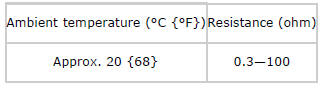
- If not as specified, replace the throttle body. (See INTAKE-AIR SYSTEM REMOVAL/INSTALLATION).
VARIABLE TUMBLE SHUTTER VALVE ACTUATOR INSPECTION
Operation Inspection
1. Disconnect the negative battery cable. (See BATTERY REMOVAL/INSTALLATION).
2. Remove the variable tumble shutter valve actuator. (See VARIABLE TUMBLE SHUTTER VALVE ACTUATOR REMOVAL/INSTALLATION).
3. Connect the battery positive voltage to terminal B or D, and verify that the gear moves.
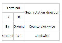
- If there is any malfunction, replace the variable tumble shutter valve
actuator.
(See VARIABLE TUMBLE SHUTTER VALVE ACTUATOR REMOVAL/INSTALLATION).
VARIABLE TUMBLE SHUTTER VALVE ACTUATOR REMOVAL/INSTALLATION
CAUTION:
- Be careful of the following after removing the actuator to prevent
abnormal gear wear
and gear lock which could result in shutter valve malfunction.
- Do not pull out the intake manifold side gear.
- Do not allow foreign material to contact the intake manifold side gear.
- Keep the inside of the actuator away from foreign material.
- Improper installation of the actuator and retainer will cause gear lock and might result in shutter valve malfunction. To prevent this, install the actuator and shutter valve as described in the following procedure:
1. Disconnect the negative battery cable. (See BATTERY REMOVAL/INSTALLATION).
2. Remove the fresh-air duct and air cleaner as a single unit. (See INTAKE-AIR SYSTEM REMOVAL/INSTALLATION).
3. Remove the battery. (See BATTERY REMOVAL/INSTALLATION).
4. Disconnect the variable tumble shutter valve actuator connector.
5. Remove in the order indicated in the table.
- Variable tumble shutter valve actuator
- Retainer
6. Install in the reverse order of removal.
Variable Tumble Shutter Valve Actuator Removal Note
1. After removing the actuator, cover it with a plastic sheet to prevent foreign material from entering the inside of the actuator.
Retainer Removal Note
1. After removing the retainer, cover it with a plastic sheet to prevent foreign material from contacting the intake manifold side gear.
Retainer Installation Note
1. Install the retainer by positioning the projection on the intake manifold with the indentation on the retainer.
2. Be careful not to shift the retainer installation position.
Variable Tumble Shutter Valve Actuator Installation Note
1. Verify that the retainer installation position has not shifted.
2. Verify that the gasket is installed.
3. Install the variable tumble shutter valve actuator.
4. Verify that intake manifold side gear and actuator side gear are engaged properly so that the actuator can be installed without any excessive force.
ACCELERATOR PEDAL REMOVAL/INSTALLATION
1. Disconnect the negative battery cable. (See BATTERY REMOVAL/INSTALLATION).
2. Remove in the order indicated in the table.
- APP sensor connector
- Accelerator pedal
3. Install in the reverse order of removal.

