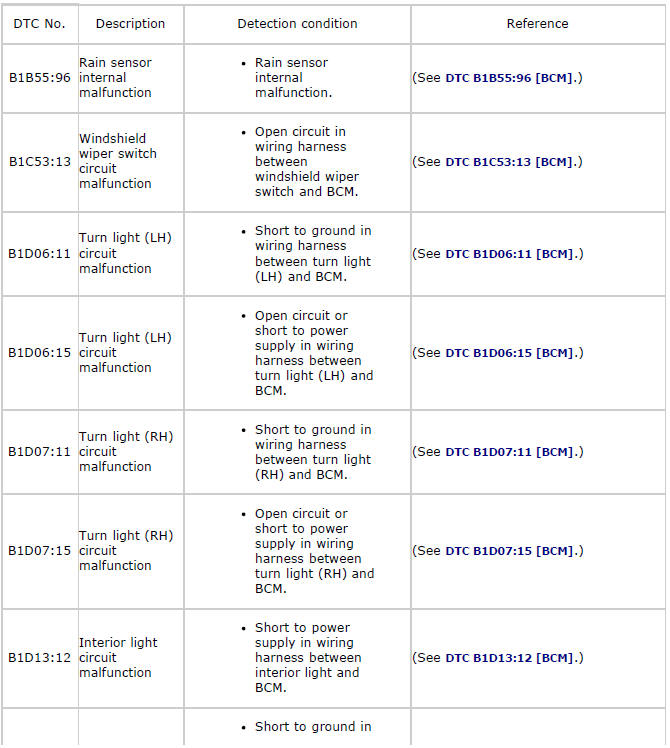
Mazda 2: DTC Table [BCM]
*1 ATX
DTC B1B55:96
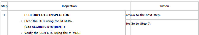
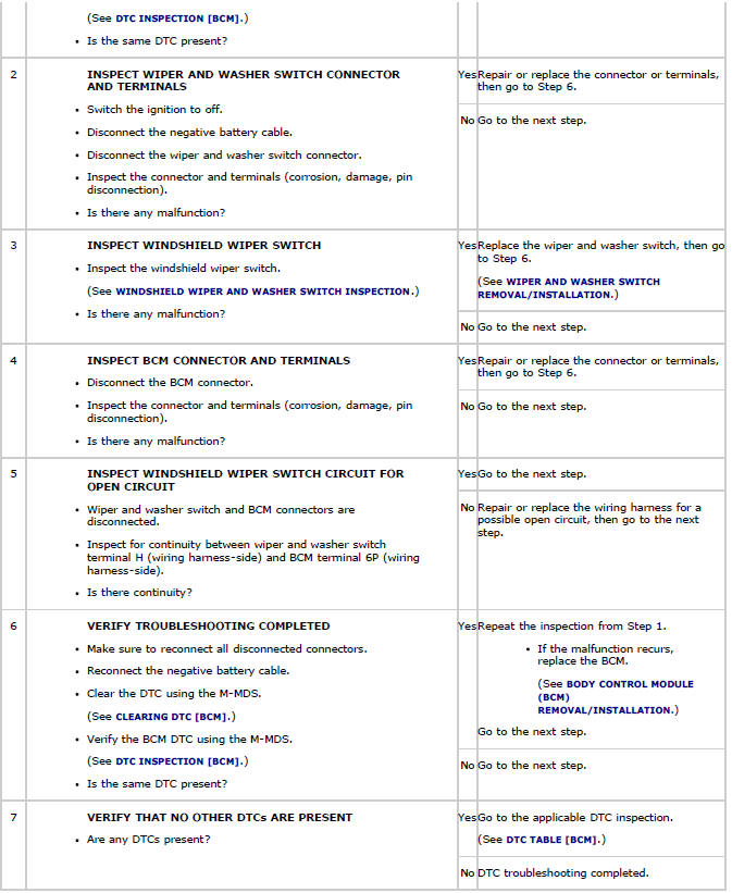
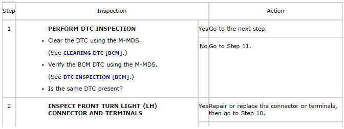
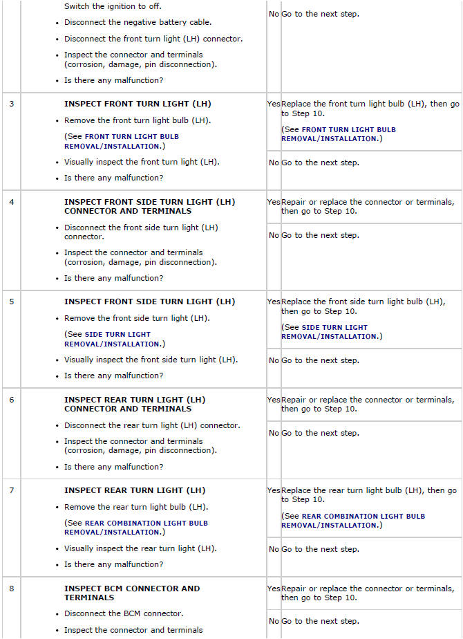
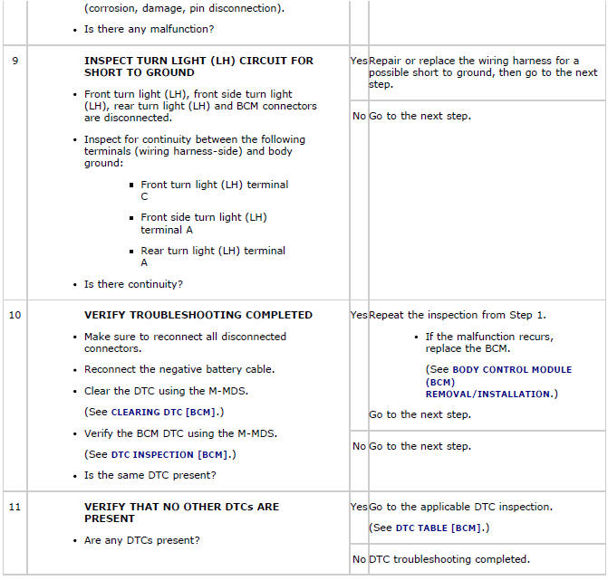
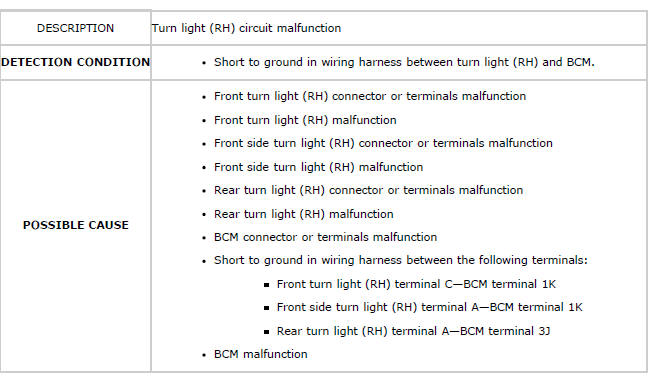
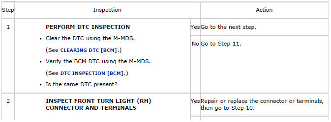
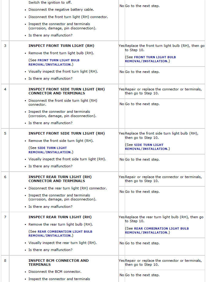
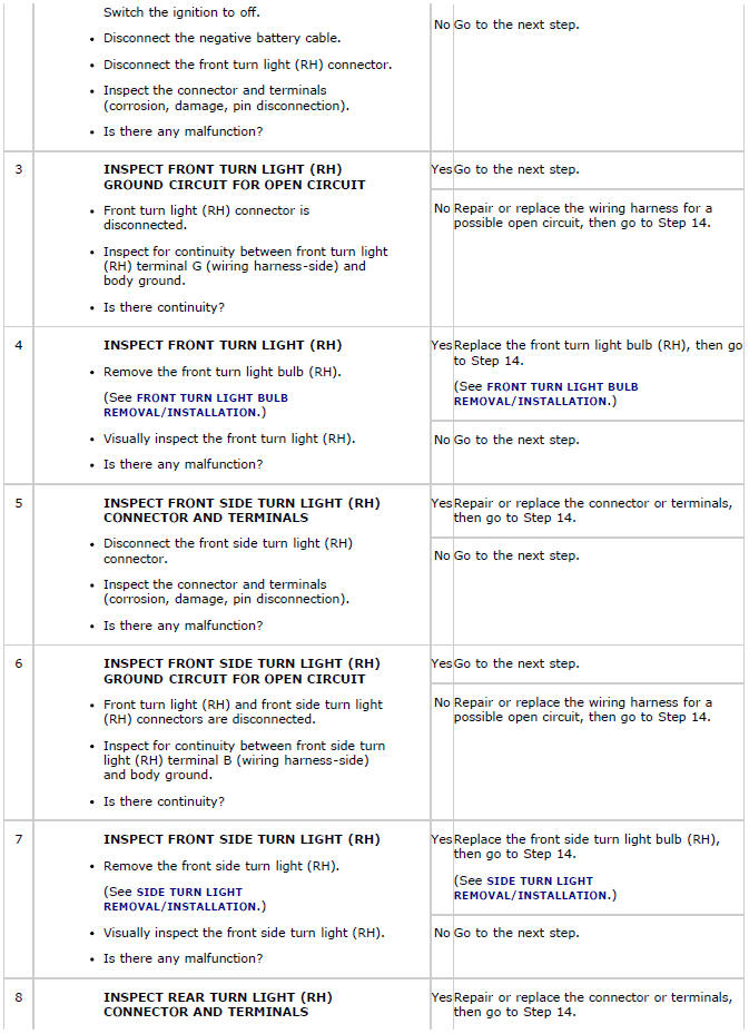
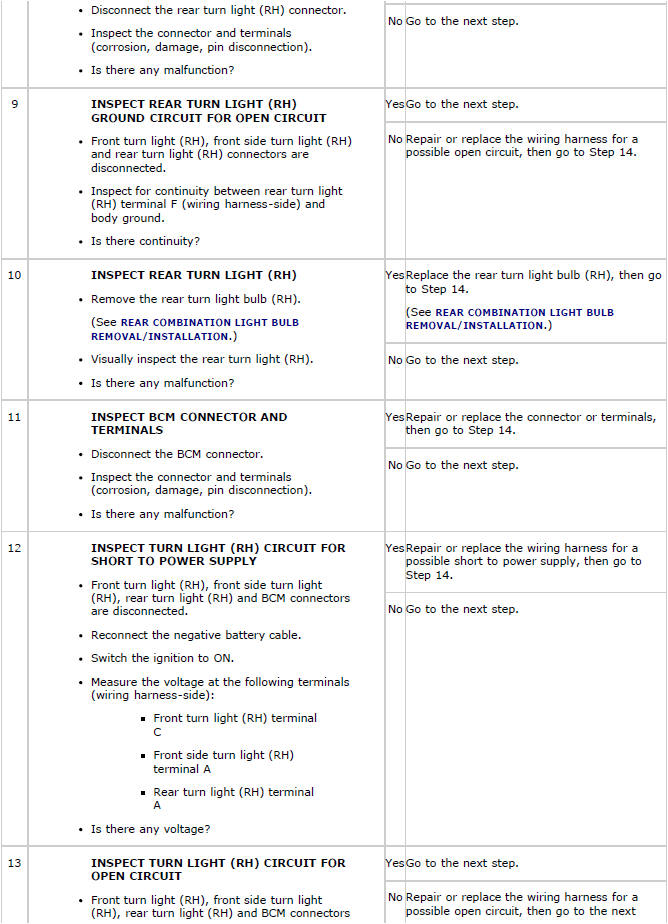
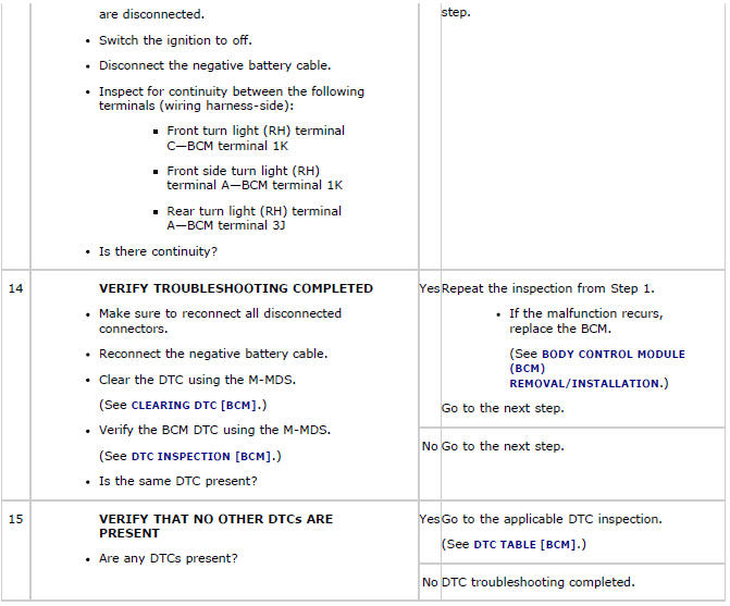
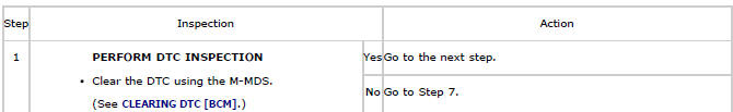
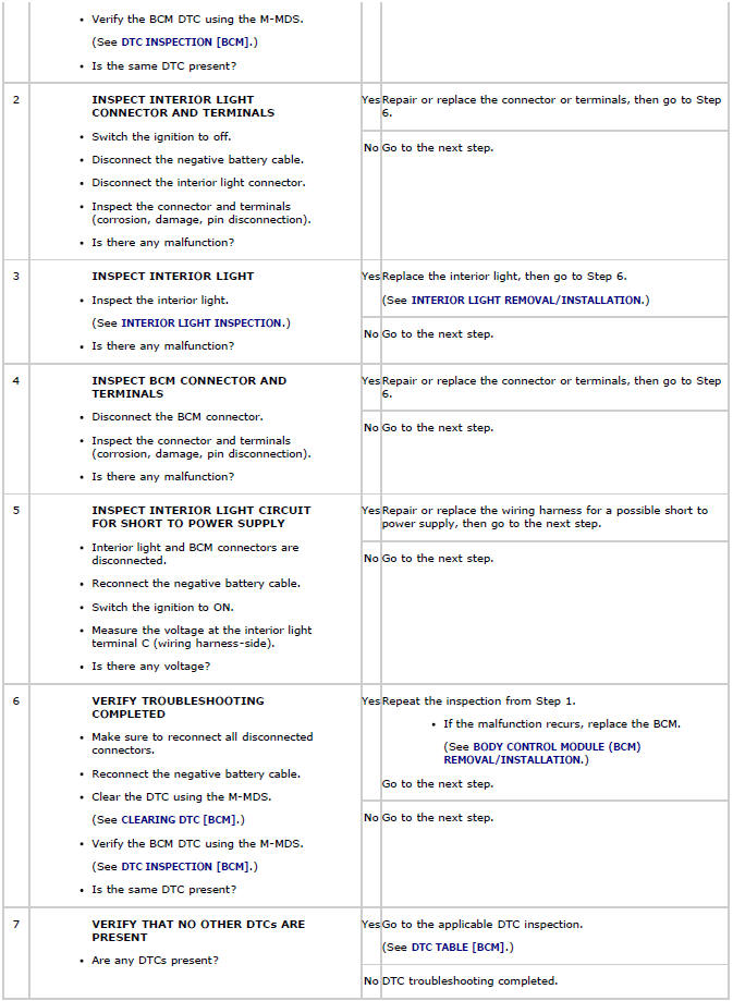
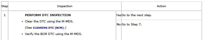
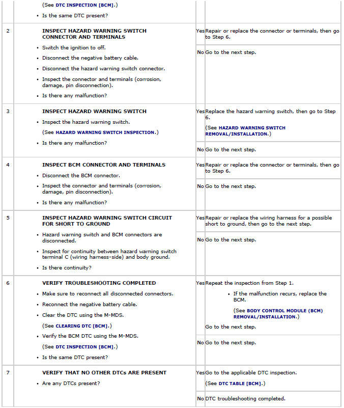
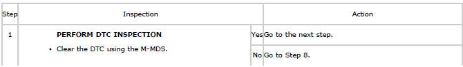
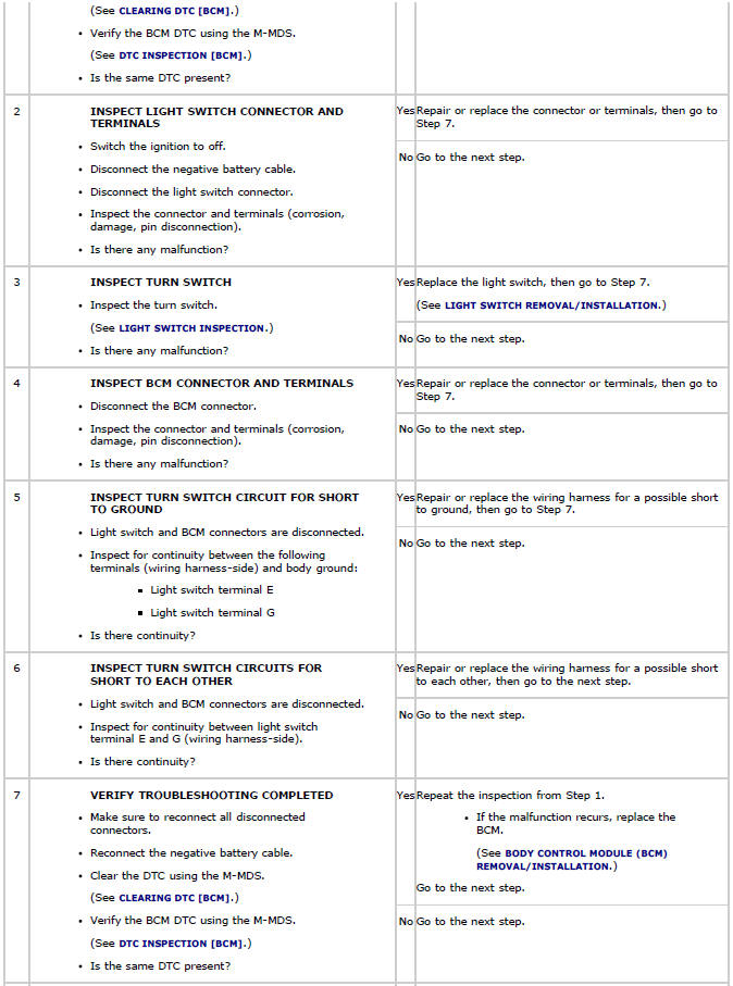
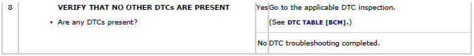
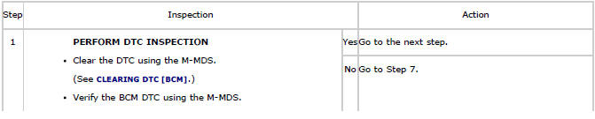
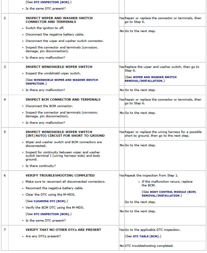
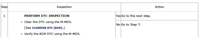
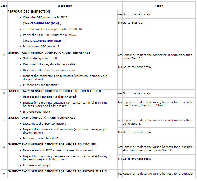
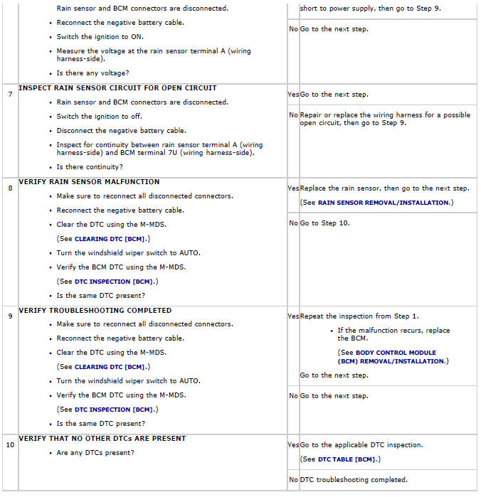
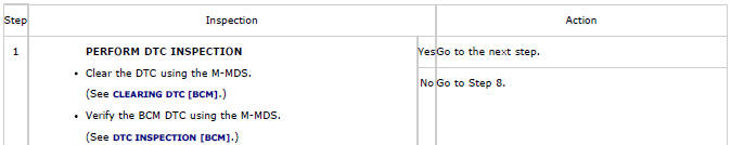
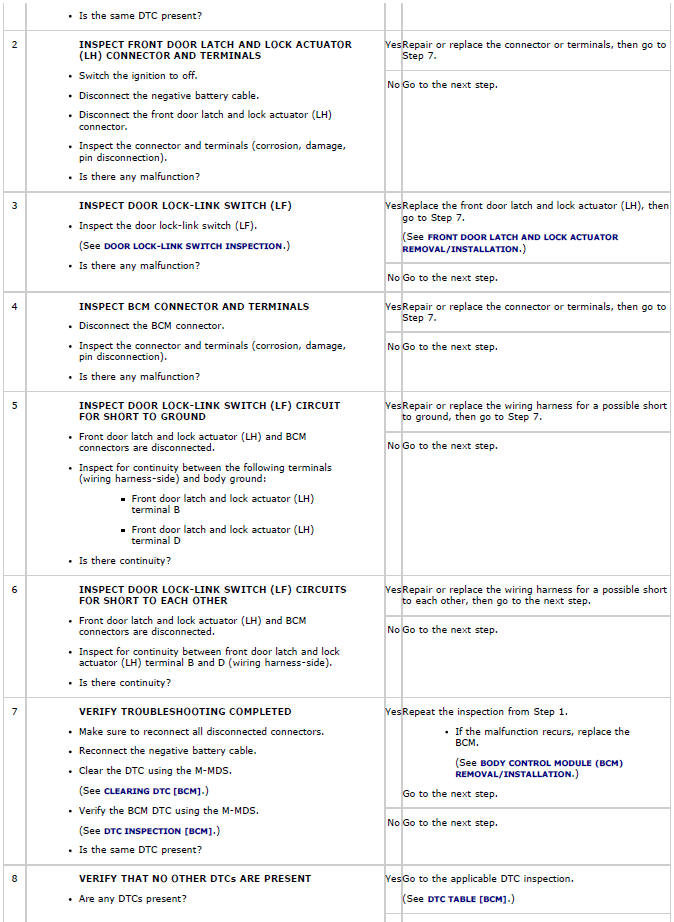
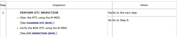
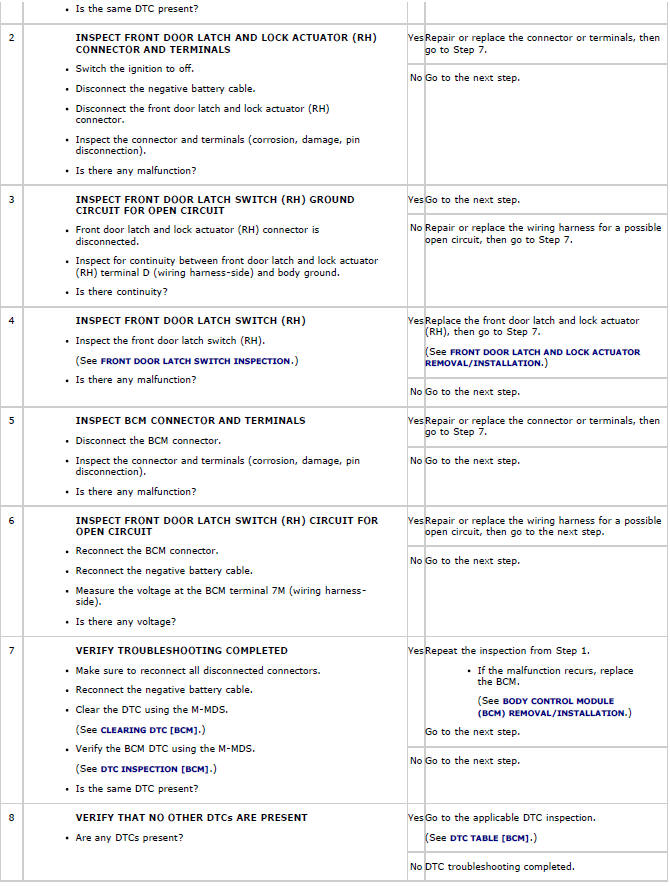
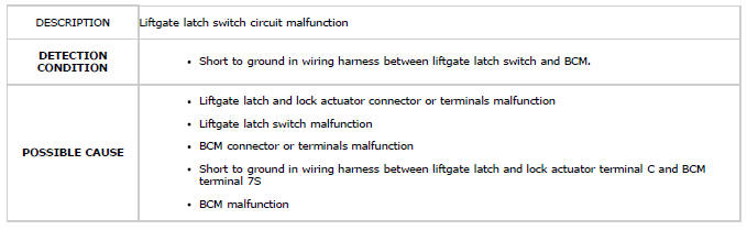
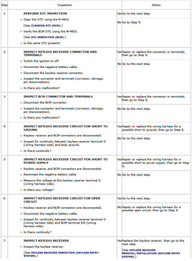
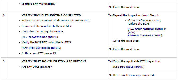
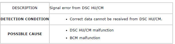
Diagnostic procedure
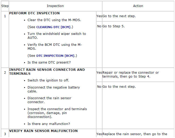
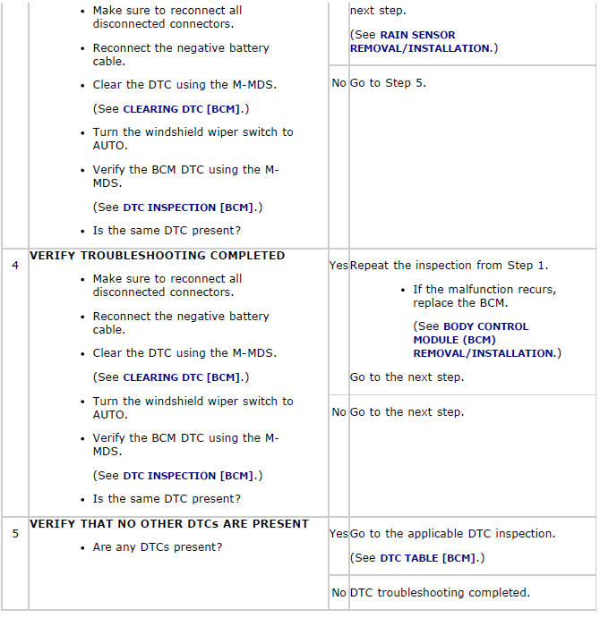
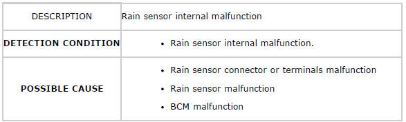
DTC B1C53:13
System Wiring Diagram

Diagnostic Procedure
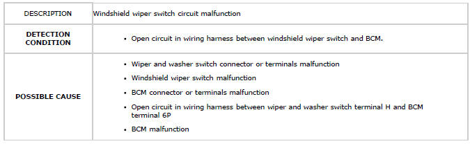
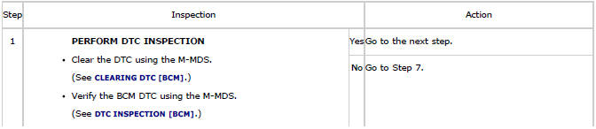
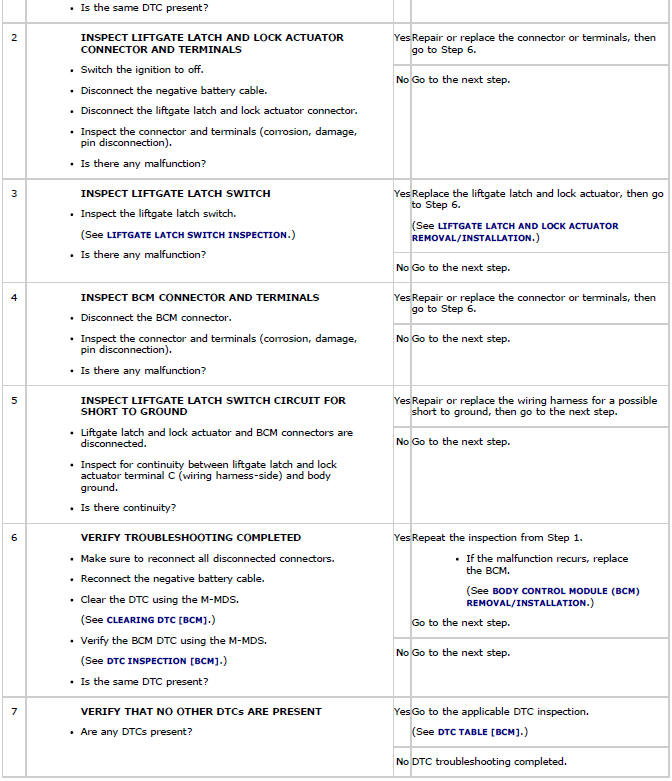
DTC B1D06:11
System Wiring Diagram
Diagnostic Procedure
DTC B1D06:15
System Wiring Diagram
Diagnostic Procedure

DTC B1D07:11
System Wiring Diagram
Diagnostic Procedure
DTC B1D07:15
System Wiring Diagram
Diagnostic Procedure
DTC B1D13:12
System Wiring Diagram
Diagnostic Procedure
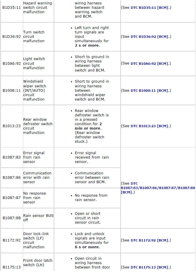
DTC B1D35:11
System Wiring Diagram
Diagnostic Procedure
DTC B1D36:92
System Wiring Diagram
Diagnostic Procedure
DTC B10A6:92
System Wiring Diagram
Diagnostic procedure

DTC B1008:11
System wiring diagram
Diagnostic Procedure
DTC B1013:23
System Wiring Diagram
Diagnostic Procedure
DTC B1087:83/B1087:86/B1087:87/B1087:88
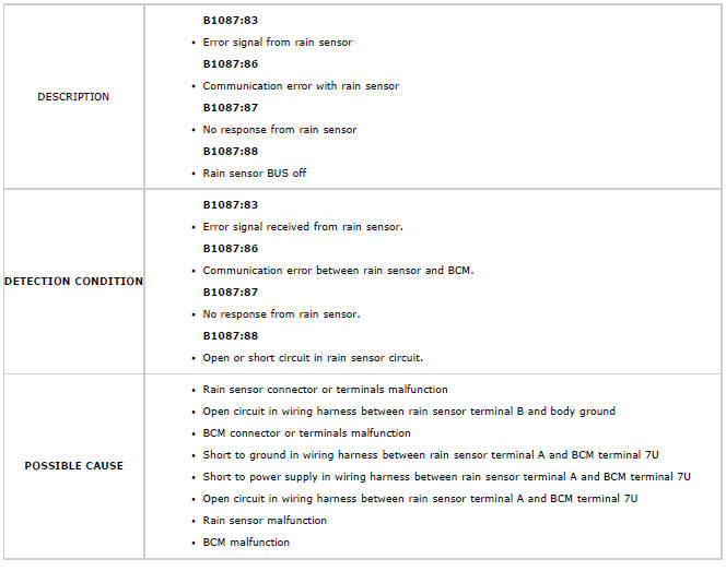
System Wiring Diagram
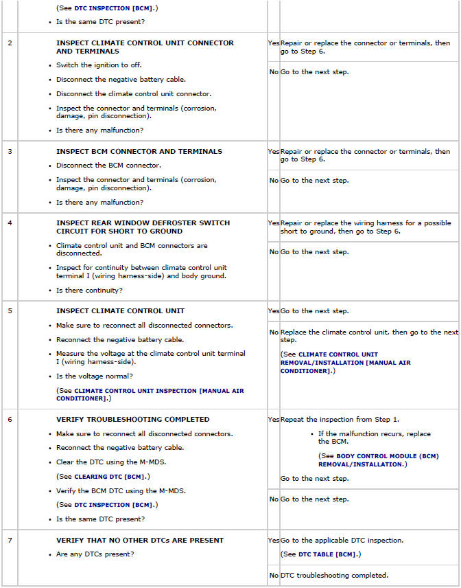
Diagnostic procedure
DTC B1172:92
System Wiring Diagram
Diagnostic Procedure

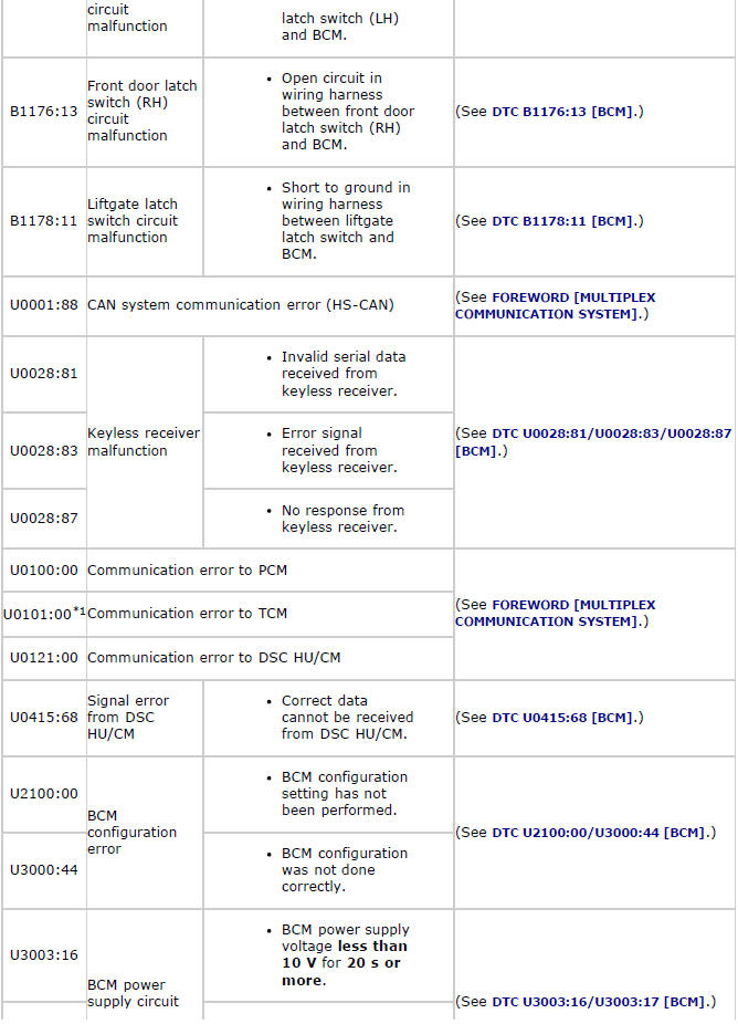
DTC B1175:13
System Wiring Diagram
Diagnostic Procedure
DTC B1176:13
System Wiring Diagram
Diagnostic Procedure
DTC B1178:11
System Wiring Diagram
Diagnostic Procedure
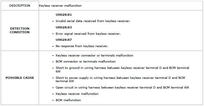
DTC U0028:81/U0028:83/U0028:87
System Wiring Diagram
Diagnostic Procedure
DTC U0415:68
Diagnostic Procedure
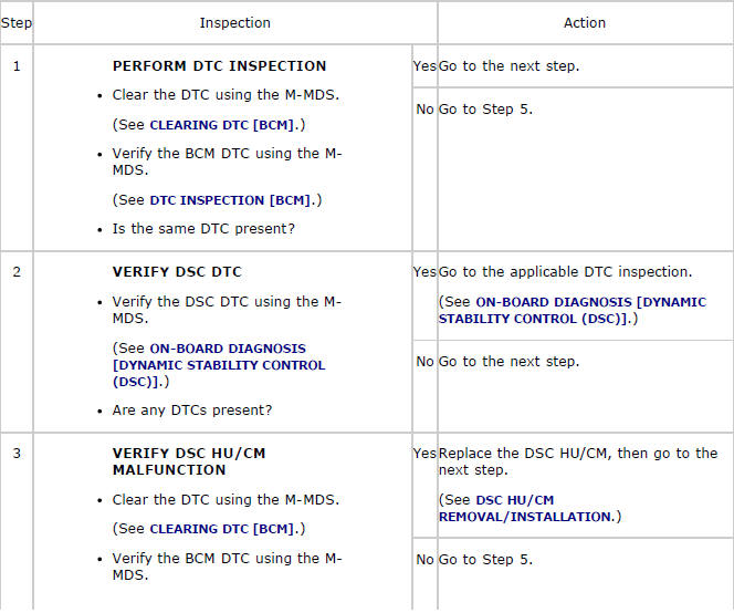
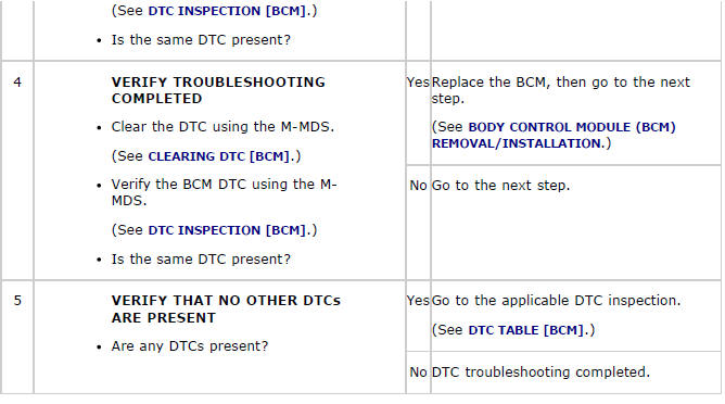
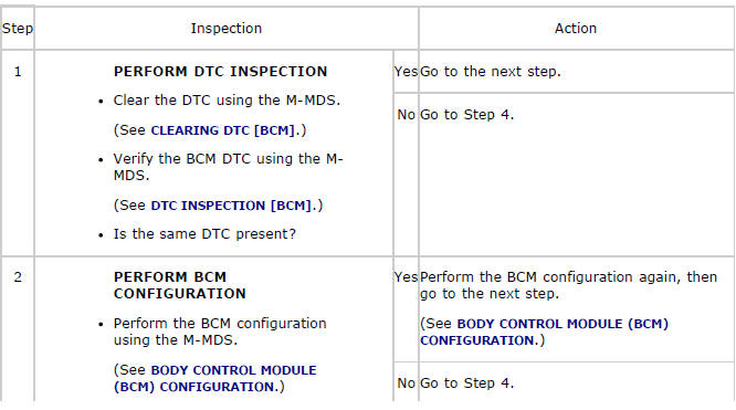
DTC U2100:00/U3000:44
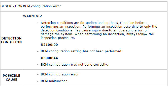
Diagnostic Procedure
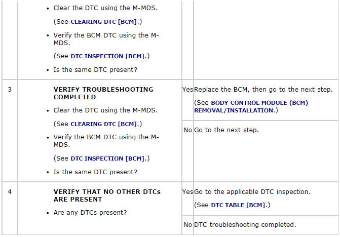
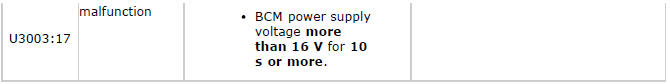
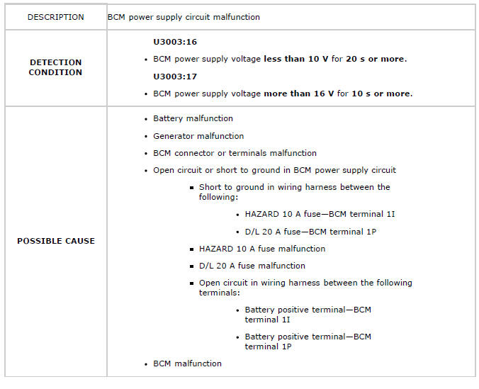
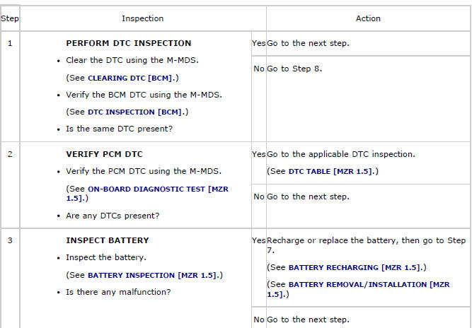
DTC U3003:16/U3003:17
System Wiring Diagram
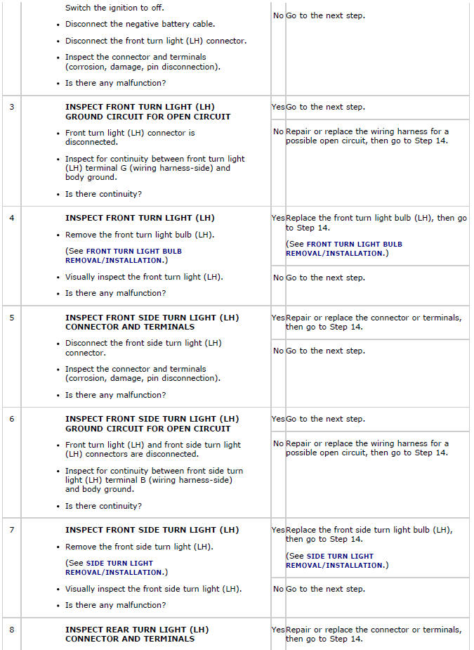
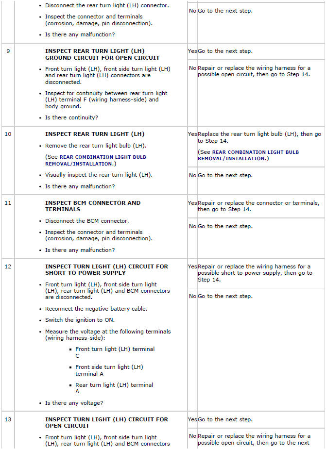
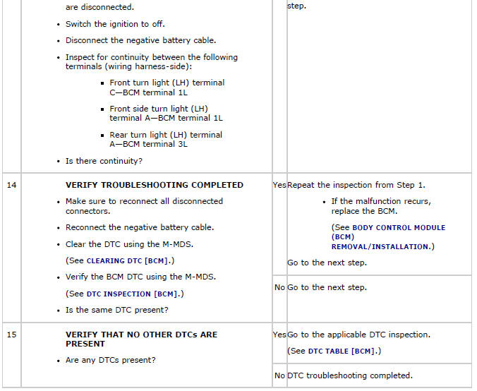
Diagnostic Procedure
PID/DATA MONITOR INSPECTION
1. Connect the M-MDS (IDS) to the DLC-2.
2. After the vehicle is identified, select the following items from the initialization screen of the IDS.
- Select "DataLogger".
- Select "Modules".
- Select "BCM/GEM".
3. Select the applicable PID from the PID table.
4. Verify the PID data according to the directions on the screen.
NOTE:
- The PID data screen function is used for monitoring the calculated value of input/output signals in the module. Therefore, if the monitored value of the output parts is not within the specification, it is necessary to inspect the monitored value of input parts corresponding to the applicable output part control. In addition, because the system does not display an output part malfunction as an abnormality in the monitored value, it is necessary to inspect the output parts individually.
PID/DATA MONITOR TABLE
![Mazda 2. PID/DATA MONITOR TABLE [BCM]](images/books/1059/mazda_2_dtc_table_bcm__2896.jpg)
![Mazda 2. PID/DATA MONITOR TABLE [BCM]](images/books/1059/mazda_2_dtc_table_bcm__2897.jpg)
![Mazda 2. PID/DATA MONITOR TABLE [BCM]](images/books/1059/mazda_2_dtc_table_bcm__2898.jpg)

