Mazda 2: A/C Unit
A/C UNIT REMOVAL/INSTALLATION
1. Set the air intake mode to REC.
2. Disconnect the negative battery cable.
3. Collect the refrigerant. (See REFRIGERANT CHARGING).
4. Drain the engine coolant. (See ENGINE COOLANT REPLACEMENT).
5. Remove the following parts:
- Glove compartment (See GLOVE COMPARTMENT REMOVAL/INSTALLATION).
- Dashboard under cover (See DASHBOARD UNDER COVER REMOVAL/INSTALLATION).
- Heat duct (RH) (See HEAT DUCT COMPONENT REMOVAL/INSTALLATION).
- Rear console (See REAR CONSOLE REMOVAL/INSTALLATION).
- Shift lever knob (MTX) (See MANUAL TRANSAXLE SHIFT MECHANISM REMOVAL/INSTALLATION).
- Side wall (See SIDE WALL REMOVAL/INSTALLATION).
- Front console component (See FRONT CONSOLE COMPONENT REMOVAL/INSTALLATION).
- Front scuff plate (See FRONT SCUFF PLATE REMOVAL/INSTALLATION).
- Front side trim (See FRONT SIDE TRIM REMOVAL/INSTALLATION).
- Hood release lever (See HOOD LATCH AND RELEASE LEVER REMOVAL/INSTALLATION).
- Driver's side lower panel (See LOWER PANEL REMOVAL/INSTALLATION).
- Knee bolster (See KNEE BOLSTER REMOVAL/INSTALLATION).
- Driver-side air bag module (See DRIVER-SIDE AIR BAG MODULE REMOVAL/INSTALLATION).
- Steering wheel (See STEERING WHEEL AND COLUMN REMOVAL/INSTALLATION).
- Column cover (See COLUMN COVER REMOVAL/INSTALLATION).
- Meter hood (See METER HOOD REMOVAL/INSTALLATION).
- Instrument cluster (See INSTRUMENT CLUSTER REMOVAL/INSTALLATION).
- Combination switch (See COMBINATION SWITCH REMOVAL/INSTALLATION).
- Center panel unit (See CENTER PANEL UNIT REMOVAL/INSTALLATION).
- Climate control unit (See CLIMATE CONTROL UNIT REMOVAL/INSTALLATION [MANUAL AIR CONDITIONER] ).
- Shift lever (MTX) (See MANUAL TRANSAXLE SHIFT MECHANISM REMOVAL/INSTALLATION).
- Selector lever (ATX) (See AUTOMATIC TRANSAXLE SHIFT MECHANISM REMOVAL/INSTALLATION).
- Interlock unit (ATX) (See AUTOMATIC TRANSAXLE SHIFT MECHANISM REMOVAL/INSTALLATION).
- Passenger's side lower panel (See LOWER PANEL REMOVAL/INSTALLATION).
- Side panel (See SIDE PANEL REMOVAL/INSTALLATION).
- A-pillar trim (See A-PILLAR TRIM REMOVAL/INSTALLATION).
- Windshield wiper arm and blade (See WINDSHIELD WIPER ARM AND BLADE REMOVAL/INSTALLATION).
- Cowl grille (See COWL GRILLE REMOVAL/INSTALLATION).
- Windshield wiper motor (See WINDSHIELD WIPER MOTOR REMOVAL/INSTALLATION).
- Sail garnish (See SAIL GARNISH REMOVAL/INSTALLATION).
- Steering shaft cover (See STEERING WHEEL AND COLUMN REMOVAL/INSTALLATION).
- Steering shaft (See STEERING WHEEL AND COLUMN REMOVAL/INSTALLATION).
6. Disconnect the vehicle wiring harnesses related to the dashboard.
7. Disconnect the antenna feeder No.1 jack.
8. Remove the dashboard. (See DASHBOARD REMOVAL/INSTALLATION).
9. Remove the air cleaner installation bolt and slide the air cleaner component aside.
10. Disconnect the heater hose from the A/C unit. (See HEATER HOSE REMOVAL/INSTALLATION).
CAUTION:
- If moisture or foreign material enters the refrigeration cycle, cooling ability will be lowered and abnormal noise or other malfunction could occur. Always plug open fittings immediately after removing any refrigeration cycle parts.
11. Using the SSTs (49 B061 014, 49 G061 001), disconnect the cooler pipe and cooler hose from the A/C unit while preventing the remaining compressor oil in the pipe and A/C unit from spilling. (See REFRIGERANT LINE REMOVAL/INSTALLATION).
12. Remove the air intake duct. (See AIR INTAKE DUCT REMOVAL/INSTALLATION).
13. Remove in the order indicated in the table.
- Cap
- A/C unit
14. Install in the reverse order of removal.
15. Perform the refrigerant system performance test. (See REFRIGERANT SYSTEM PERFORMANCE TEST).
A/C Unit Installation Note
1. When replacing the A/C unit or evaporator, add compressor oil to the refrigerant cycle.
Supplemental oil amount (approx. quantity)
- 27 ml {27 cc, 0.91 fl oz}
A/C UNIT DISASSEMBLY/ASSEMBLY
1. Disassemble in the order indicated in the figure.
CAUTION:
- If a non-specified grease is used, it may result in abnormal noise or improper operation of the links. Apply only the specified grease to each link.
2. Assemble in the reverse order of disassembly.
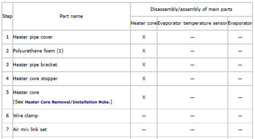
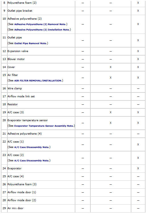
X Applicable
Heater Core Removal/Installation Note
CAUTION:
- When removing or installing the heater core, hold the heater core side of the pipe connecting area. Holding the pipe side may cause a bend on the crimped area of the pipe connecting area, resulting in heater core damage.
Adhesive Polyurethane (2) Removal Note
CAUTION:
- Because of the possibility of condensation forming, whenever possible remove the adhesive polyurethane carefully so that it does not damage the adhesive sponge rubber on the outlet pipe.
Outlet Pipe Removal Note
1. Make a hole in the position shown in the figure for the adhesive polyurethane (2) and install the outlet pipe installation bolt.
Tightening Torque
- 6.8-9.8 N*m {70-99 kgf*cm, 61-86 in*lbf}
2. Tear off the adhesive polyurethane (2) from the joint area of the expansion valve and outlet pipe.
3. Remove the outlet pipe from the expansion valve.
A/C Case Disassembly Note
1. Cut the adhesive polyurethane (4) along the contacting surfaces of the case.
Evaporator Temperature Sensor Assembly Note
1. Assemble the evaporator temperature sensor as shown in the figure.
CAUTION:
- When installing the evaporator temperature sensor without newly replacing the evaporator, assemble the evaporator temperature sensor with the installation position slid to the left of the previous position by 1 line. If the evaporator temperature sensor is assembled to the previously installed position, it may not function due to poor contact of the fin surface with the sensor detection area caused by fin deformation.
NOTE:
- Newly replace an evaporator in which the evaporator temperature sensor cannot be correctly positioned.
Adhesive Polyurethane (2) Installation Note
1. Align the adhesive polyurethane (2) notch with the center of the lower surface of the expansion valve, and adhere.
2. Roll on the adhesive polyurethane (2) so that it wraps around the expansion valve.
3. Bend around the adhesive polyurethane (2) and adhere it to the outlet pipe.