Mazda 2: Door and Liftgate
DOOR AND LIFTGATE LOCATION INDEX
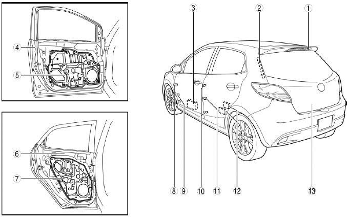
- Liftgate hinge
- Stay damper
- Front door pad
- Front door
- Front door module panel
- Rear door
- Rear door module panel
- Front door hinge
- Front door checker
- Rear door hinge
- Rear door checker
- Rear door pad
- Liftgate
FRONT DOOR REMOVAL/INSTALLATION
WARNING:
- Removing the front door without supporting it could cause the front door to fall and cause serious injury. Always perform the procedure with at least another person to prevent the front door from falling.
1. Disconnect the negative battery cable.
2. Remove in the order indicated in the table.
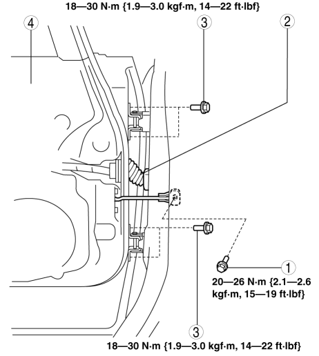
- Bolt A
- Connector
- Bolt B
- Front door
3. Install in the reverse order of removal.
4. Adjust the front door. (See DOOR ADJUSTMENT).
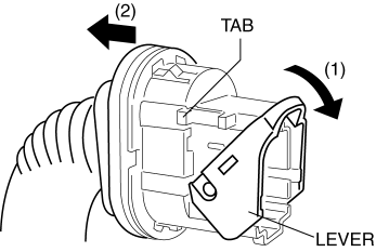
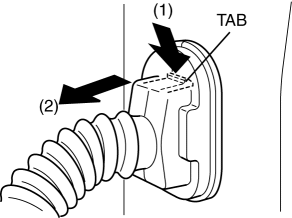
Connector Removal Note
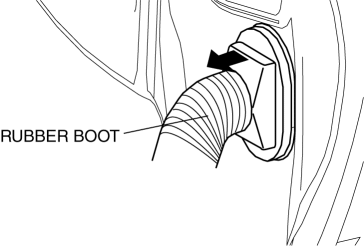
1. Pull the rubber boot outward.
2. Press the tab in the direction of arrow (1) shown in the figure using a tape-wrapped flathead screwdriver, and remove the connector from the body in the direction of arrow (2) shown in the figure.
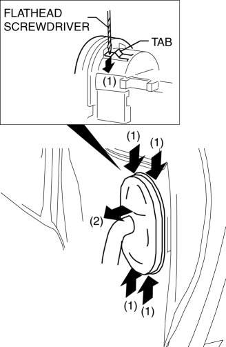
3. Lower the lever in the direction of arrow (1), and disconnect the connector in the direction of arrow (2).
FRONT DOOR MODULE PANEL REMOVAL/INSTALLATION
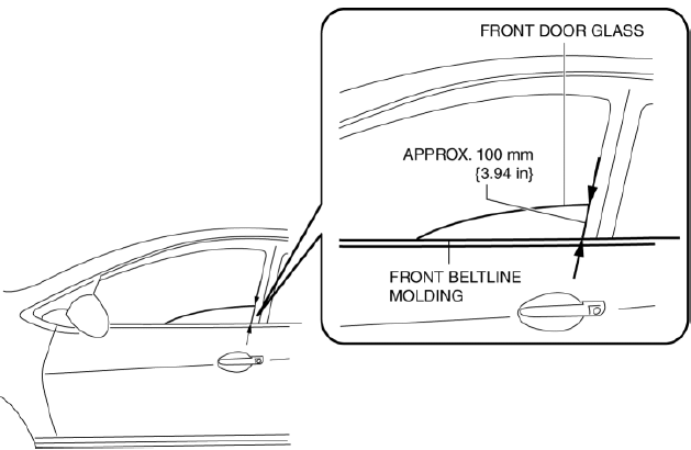
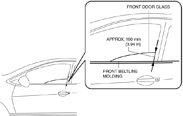
1. To access the glass installation bolt, position the front door glass so that the distance from the top of the front door glass to the upper part of the front beltline molding is approx. 100 mm {3.94 in}.
2. Disconnect the negative battery cable.
3. Remove the following parts:
- Inner garnish (See INNER GARNISH REMOVAL/INSTALLATION).
- Front door trim (See FRONT DOOR TRIM REMOVAL/INSTALLATION).
- Front door speaker (See FRONT DOOR SPEAKER REMOVAL/INSTALLATION).
- Front door glass (See FRONT DOOR GLASS REMOVAL/INSTALLATION).
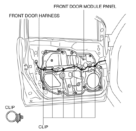
4. Remove the clips securing the front door wiring harness from the front door module panel.
5. Remove the bolts.
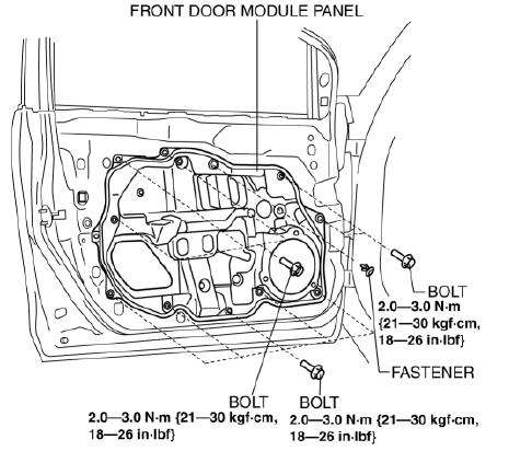
6. Remove the fastener.
7. Remove the front door module panel.
8. Remove the front power window motor. (See POWER WINDOW MOTOR REMOVAL/INSTALLATION).
9. Remove the front power window regulator. (See FRONT POWER WINDOW REGULATOR REMOVAL/INSTALLATION).
10. Install in the reverse order of removal.
FRONT DOOR PAD REMOVAL/INSTALLATION
1. To access the glass installation bolt, position the front door glass so that the distance from the top of the front door glass to the upper part of the front beltline molding is approx. 100 mm 3.94{in}.
2. Disconnect the negative battery cable.
3. Remove the following parts:
- Inner garnish (See INNER GARNISH REMOVAL/INSTALLATION).
- Front door trim (See FRONT DOOR TRIM REMOVAL/INSTALLATION).
- Front door speaker (See FRONT DOOR SPEAKER REMOVAL/INSTALLATION).
- Front door glass (See FRONT DOOR GLASS REMOVAL/INSTALLATION).
- Front door module panel (See FRONT DOOR MODULE PANEL REMOVAL/INSTALLATION).
4. Remove the fasteners.
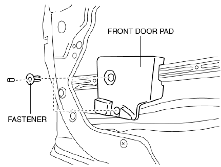
5. Remove the front door pad.
6. Remove the double-sided adhesive tape on the front door pad and body using a utility knife.
WARNING:
- Using a utility knife with bare hands can cause injury. Always wear gloves when using a razor.
7. Install in the reverse order of removal.
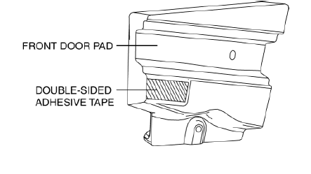
- When reusing the front door pad, affix double-sided adhesive tape to the front door pad as shown in the figure.
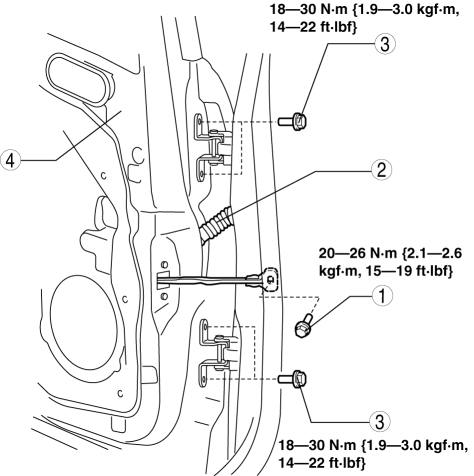
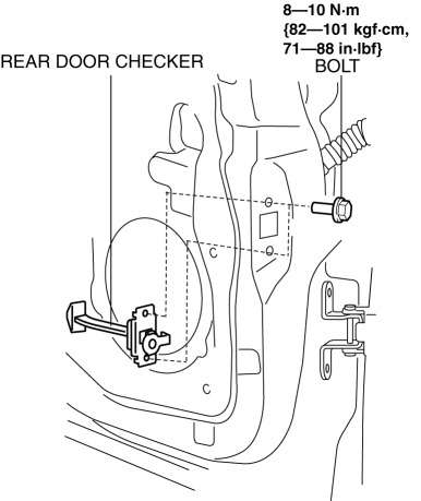
FRONT DOOR CHECKER REMOVAL/INSTALLATION
1. Fully close the front door glass.
2. Disconnect the negative battery cable.
3. Remove the inner garnish. (See INNER GARNISH REMOVAL/INSTALLATION).
4. Remove the front door trim. (See FRONT DOOR TRIM REMOVAL/INSTALLATION).
5. Remove the front door speaker. (See FRONT DOOR SPEAKER REMOVAL/INSTALLATION).
6. Remove the bolt.
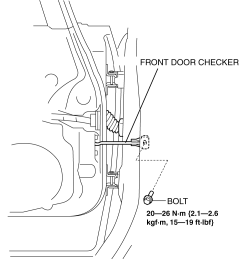
7. Remove the bolts.
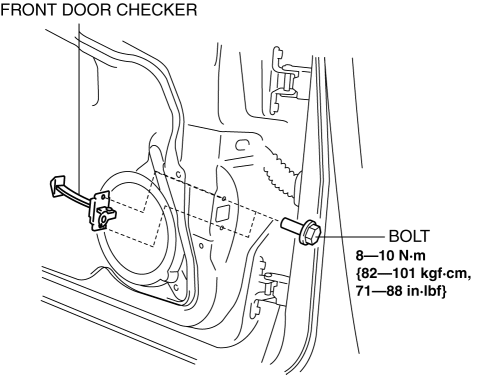
8. Pull out the front door checker from the front speaker installation hole.
9. Install in the reverse order of removal.
FRONT DOOR HINGE REMOVAL/INSTALLATION
1. Disconnect the negative battery cable.
2. Remove the following parts:
- Sail garnish (See SAIL GARNISH REMOVAL/INSTALLATION)
- Front side turn light (See SIDE TURN LIGHT REMOVAL/INSTALLATION).
- Front bumper (See FRONT BUMPER REMOVAL/INSTALLATION).
- Front combination light (See FRONT COMBINATION LIGHT REMOVAL/INSTALLATION).
- Side step molding (vehicles with side step molding) (See SIDE STEP MOLDING REMOVAL). (See SIDE STEP MOLDING INSTALLATION).
- Front fender panel (See FRONT FENDER PANEL REMOVAL/INSTALLATION).
- Front door (See FRONT DOOR REMOVAL/INSTALLATION).
3. Remove in the order indicated in the table.
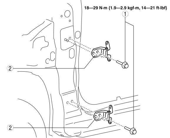
- Bolt
- Front door hinge
4. Install in the reverse order of removal.
REAR DOOR REMOVAL/INSTALLATION
WARNING:
- Removing the rear door without supporting it could cause the rear door to fall and cause serious injury. Always perform the procedure with at least another person to prevent the rear door from falling.
1. Disconnect the negative battery cable.
2. Remove in the order indicated in the table.
- Bolt A
- Connector
- Bolt B
- Rear door
3. Install in the reverse order of removal.
4. Adjust the rear door. (See DOOR ADJUSTMENT).
Connector Removal Note
1. While pressing the tab in the direction of arrow (1), disconnect the connector in the direction of arrow (2).
REAR DOOR MODULE PANEL REMOVAL/INSTALLATION
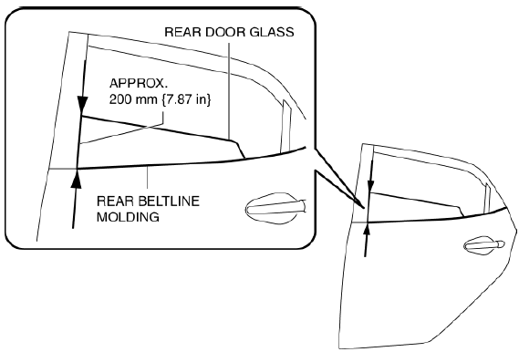
1. To access the glass installation bolt, position the rear door glass so that the distance from the top of the rear door glass to the upper part of the rear beltline molding is approx. 200 mm {7.87 in}.
2. Disconnect the negative battery cable.
3. Remove the following parts:
- Sail inner garnish (See SAIL INNER GARNISH REMOVAL/INSTALLATION).
- Rear door garnish (See REAR DOOR GARNISH REMOVAL/INSTALLATION).
- Rear door trim (See REAR DOOR TRIM REMOVAL/INSTALLATION).
- Rear door speaker (See REAR DOOR SPEAKER REMOVAL/INSTALLATION).
- Rear door glass (See REAR DOOR GLASS REMOVAL/INSTALLATION).
4. Remove the clips securing the rear door wiring harness from the rear door module panel.
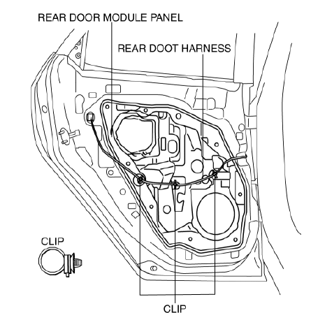
5. Remove the bolts.
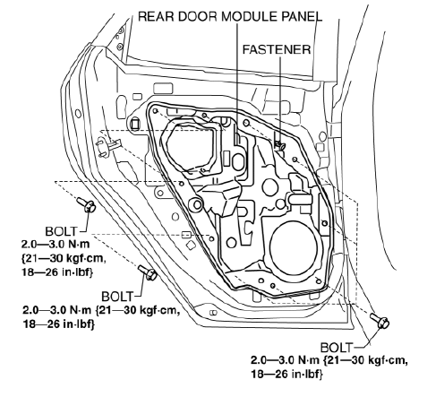
6. Remove the fastener.
7. Remove the rear door module panel.
8. Remove the rear power window motor. (See POWER WINDOW MOTOR REMOVAL/INSTALLATION).
9. Remove the rear power window regulator. (See REAR POWER WINDOW REGULATOR REMOVAL/INSTALLATION).
10. Install in the reverse order of removal.
REAR DOOR PAD REMOVAL/INSTALLATION
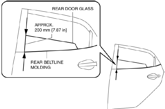
1. To access the glass installation bolt, position the rear door glass so that the distance from the top of the rear door glass to the upper part of the rear beltline molding is approx. 200 mm {7.87 in}.
2. Disconnect the negative battery cable.
3. Remove the following parts:
- Sail inner garnish (See SAIL INNER GARNISH REMOVAL/INSTALLATION).
- Rear door garnish (See REAR DOOR GARNISH REMOVAL/INSTALLATION).
- Rear door trim (See REAR DOOR TRIM REMOVAL/INSTALLATION).
- Rear door speaker (See REAR DOOR SPEAKER REMOVAL/INSTALLATION).
- Rear door glass (See REAR DOOR GLASS REMOVAL/INSTALLATION).
- Rear door module panel (See REAR DOOR MODULE PANEL
4. Remove the fasteners.
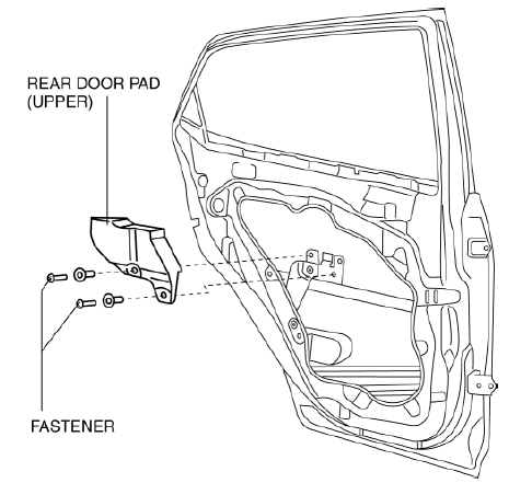
5. Remove the rear door pad (upper).
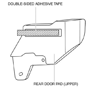
6. Remove the double-sided adhesive tape on the rear door pad (upper) and body using a utility knife.
WARNING:
- Using a utility knife with bare hands can cause injury. Always wear gloves when using a razor.
7. Remove the fasteners.
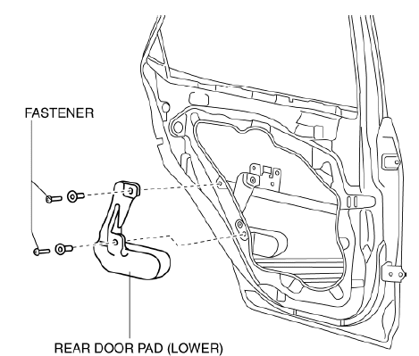
8. Remove the rear door pad (lower).
9. Install in the reverse order of removal.
- When reusing the rear door pad (upper), affix double-sided adhesive tape to the rear door pad (upper) as shown in the figure.
REAR DOOR CHECKER REMOVAL/INSTALLATION
1. Fully close the rear door glass.
2. Disconnect the negative battery cable.
3. Remove the sail inner garnish. (See SAIL INNER GARNISH REMOVAL/INSTALLATION).
4. Remove the rear door trim. (See REAR DOOR TRIM REMOVAL/INSTALLATION).
5. Remove the rear door speaker. (See REAR DOOR SPEAKER REMOVAL/INSTALLATION).
6. Remove the bolt.
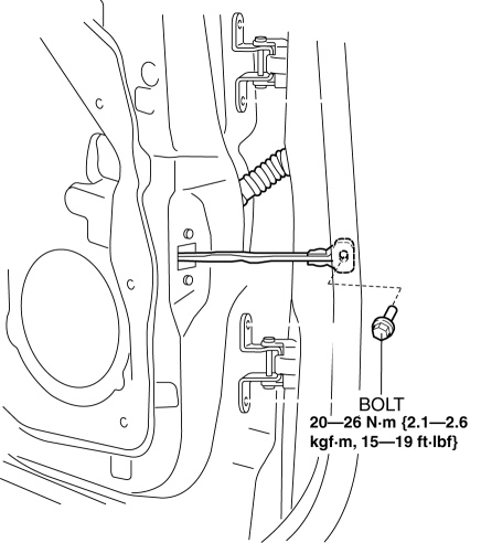
7. Remove the bolts.
8. Pull out the rear door checker from the rear speaker installation hole.
9. Install in the reverse order of removal.
REAR DOOR HINGE REMOVAL/INSTALLATION
1. Disconnect the negative battery cable.
2. Remove the following parts:
- Rear door (See REAR DOOR REMOVAL/INSTALLATION).
- Front scuff plate (See FRONT SCUFF PLATE REMOVAL/INSTALLATION).
- Rear scuff plate (See REAR SCUFF PLATE REMOVAL/INSTALLATION).
- B-pillar lower trim (See B-PILLAR LOWER TRIM REMOVAL/INSTALLATION).
3. Remove in the order indicated in the table.
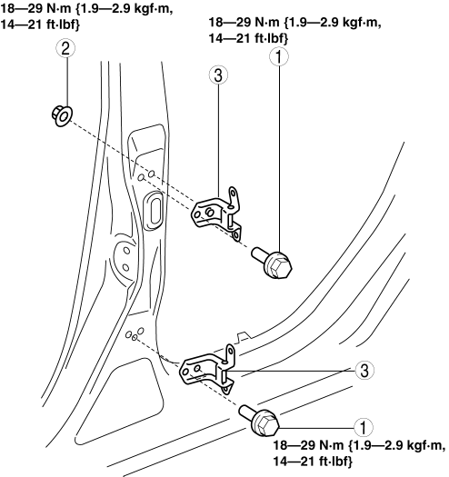
- Bolts
- Nut
- Rear door hinge
4. Install in the reverse order of removal.
LIFTGATE REMOVAL/INSTALLATION
NOTE:
- If the liftgate cannot be locked or opened due to a discharged battery or malfunctions in the electrical system, open the liftgate using the liftgate manual open/close procedure. (See LIFTGATE MANUAL OPEN/CLOSE PROCEDURE).
WARNING:
- When removing the stay damper, serious injury may occur if the stay damper is removed without supporting the liftgate. Always perform the procedure with at least another person.
1. Disconnect the negative battery cable.
2. Remove the liftgate upper trim. (See LIFTGATE UPPER TRIM REMOVAL/INSTALLATION).
3. Remove the liftgate lower trim. (See LIFTGATE LOWER TRIM REMOVAL/INSTALLATION).
4. Disconnect the connectors.
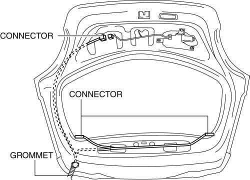
5. Remove the grommets from the liftgate.
NOTE:
- If the liftgate is to be replaced with a new one, remove the liftgate wiring harnesses without tying them with strings.
6. Tie each string to connectors (1) and (2) shown in the figure.
NOTE:
- Prepare two strings of 150 cm {59.1 in} or longer length.
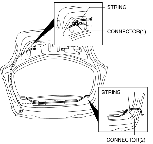
7. Pull out the liftgate wiring harness as shown in the figure while grasping the end of the string so that the end of the string does not enter the liftgate.
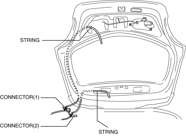
8. Untie the strings from connectors (1) and (2).
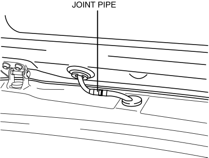
9. Disconnect the joint pipe of the rear washer hose.
10. Remove the stay damper band using a tape-wrapped flathead screwdriver.
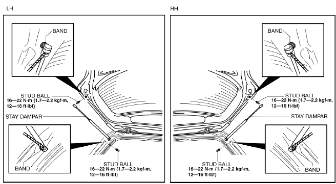
11. Remove the stay damper.
12. Remove the ball stud.
13. Remove the bolts.
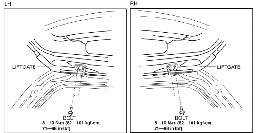
14. Remove the liftgate.
15. Install in the reverse order of removal.
16. Adjust the liftgate. (See LIFTGATE ADJUSTMENT).
LIFTGATE HINGE REMOVAL/INSTALLATION
1. Disconnect the negative battery cable.
2. Remove the following parts:
- Liftgate (See LIFTGATE REMOVAL/INSTALLATION).
- Rear scuff plate (See REAR SCUFF PLATE REMOVAL/INSTALLATION).
- Rear seat back (See REAR SEAT BACK REMOVAL/INSTALLATION).
- Rear seat cushion (See REAR SEAT CUSHION REMOVAL/INSTALLATION).
- Lower anchor installation bolts on the rear seat belt. (See REAR SEAT BELT REMOVAL/INSTALLATION)
- Trunk end trim (See TRUNK END TRIM REMOVAL/INSTALLATION).
- Trunk side trim (See TRUNK SIDE TRIM REMOVAL/INSTALLATION).
- C-pillar trim (See C-PILLAR TRIM REMOVAL/INSTALLATION).
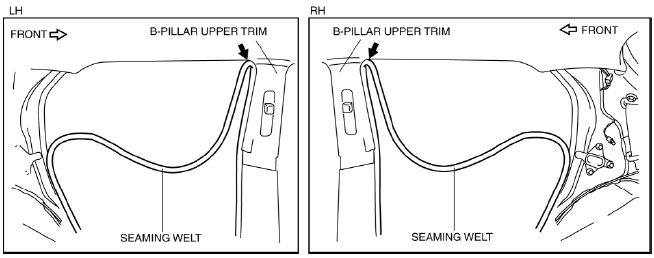
3. Peel back the seaming welt to the point indicated by the arrow in the figure.
4. Remove the fasteners on the rear part of the headliner and remove the nut while partially peeling back the headliner.
NOTE:
- Be careful not to leave a fold-seam.
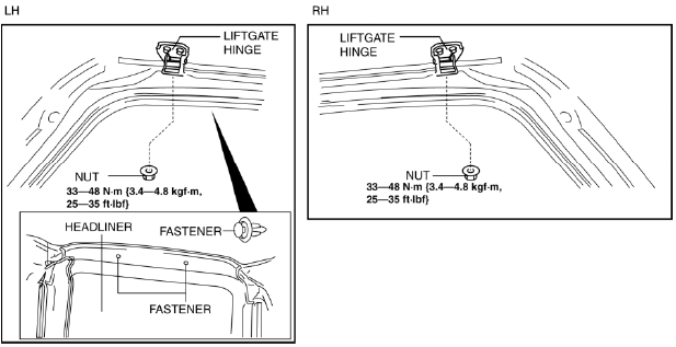
5. Remove the liftgate hinge.
6. Install in the reverse order of removal.
LIFTGATE MANUAL OPEN/CLOSE PROCEDURE
NOTE:
- If the liftgate cannot be unlocked or opened due to a discharged battery or malfunction in the electrical system, it can be opened using the following procedure.
Opening the Liftgate
1. Fold down the rear seat back.
2. Remove the liftgate lower trim. (See LIFTGATE LOWER TRIM REMOVAL/INSTALLATION).
CAUTION:
- Wear gloves when performing the procedure. The body edge can injure bare hands.
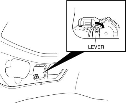
3. Move the lever shown in the figure to the left to unlock the liftgate.
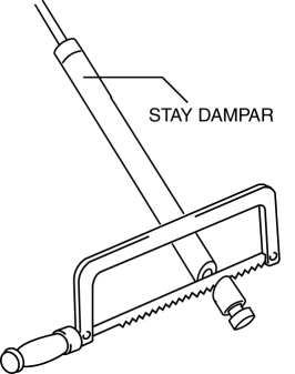
STAY DAMPER DISPOSAL
NOTE:
- The stay damper contains colorless, odorless, nontoxic gas.
1. Wear protective eye wear.
2. Position the stay damper horizontally.
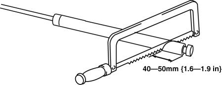
3. Drain gas and oil by cutting the position indicated in the figure to a 2-3 mm {0.08- 0.11 in} depth using a metal saw.
CAUTION:
- Be careful. The gas and oil may spray out with force.
4. Verify that the gas and oil is drained completely by pulling and pushing the piston rod several times with the cut position facing downward.
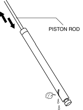
5. Cut off the bottom of the stay damper.
6. Dispose of the stay damper.
DOOR ADJUSTMENT
1. Measure the gap and height difference between the door and the body.
2. Adjust the gap and height difference to the standard range by moving the door back and forth, left and right.
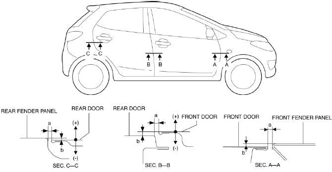
Standard range
- a: 3-5 mm {0.12-0.19 in}
- b: -1.0-1.0 mm {-0.039-0.039 in}
3. Tighten the bolts.
4. If the door does not open/close smoothly, adjust it by loosening the door lock striker installation screw.
LIFTGATE ADJUSTMENT
1. Measure the gap and height difference between the liftgate and the body.
2. Loosen the liftgate hinge installation bolts and adjust the gap by moving the liftgate.
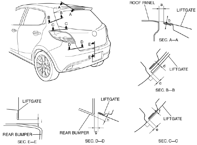
Standard clearance
- a: 5.0-7.0 mm {0.20-0.27 in}
- b: -2.0-0.0 mm {0.078-0.000 in}
- c: 2.5-6.5 mm {0.10-0.25 in}
- d: -0.2-4.2 mm {0.00-0.16 in}
- e: 2.8-5.2 mm {0.12-0.20 in}
- f: -0.7-1.7 mm {0.02-0.06 in}
- g: 2.0-6.0 mm {0.08-0.23 in}
- h: -1.5-2.5 mm {0.059-0.098 in}
- i: 4.0-8.0 mm {0.16-0.31 in}
3. Tighten the bolts.
POWER WINDOW MAIN SWITCH DISASSEMBLY/ASSEMBLY
1. Disconnect the negative battery cable.
2. Remove the inner garnish. (See INNER GARNISH REMOVAL/INSTALLATION).
3. Remove the driver's side front door trim. (See FRONT DOOR TRIM REMOVAL/INSTALLATION).
4. Remove the power window main switch. (See FRONT DOOR TRIM DISASSEMBLY/ASSEMBLY).
5. Disassemble in the order shown in the figure.
6. Assemble in the reverse order of disassembly.
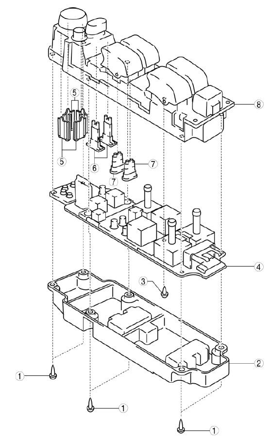
- Screw A
- Power window main switch lower housing
- Screw B
- Mother board
- Pusher A
- Pusher B
- Pusher C
- Power window main switch upper housing

