Mazda 2: Timing Chain
TIMING CHAIN REMOVAL/INSTALLATION
WARNING:
- Do not remove the jack from the engine with the bolt of engine mount No. 3 removed because the engine may fall off and cause a serious accident.
1. Disconnect the negative battery cable.
2. Drain the engine coolant. (See ENGINE COOLANT REPLACEMENT).
3. Remove the fresh-air duct and the air cleaner as a single unit. (See INTAKE-AIR SYSTEM REMOVAL/INSTALLATION).
4. Remove the ignition coils. (See IGNITION COIL REMOVAL/INSTALLATION).
5. Disconnect the ventilation hose. (See INTAKE-AIR SYSTEM REMOVAL/INSTALLATION).
6. Remove the vacuum hose bracket installation bolt, then set the vacuum hose bracket out of the way.
7. Set the cooler pipe and the cooler hose out of the way. (See REFRIGERANT LINE REMOVAL/INSTALLATION).
8. Remove the OCV. (See OIL CONTROL VALVE (OCV) REMOVAL/INSTALLATION).
9. Remove the drive belt. (See DRIVE BELT REMOVAL/INSTALLATION).
10. Remove the crankshaft position (CKP) sensor. (See CRANKSHAFT POSITION (CKP) SENSOR REMOVAL/INSTALLATION).
11. Remove the generator. (See GENERATOR REMOVAL/INSTALLATION).
12. Remove the water pump. (See WATER PUMP REMOVAL/INSTALLATION).
13. Remove in the order indicated in the table.
14. Install in the reverse order of removal.
15. Start the engine, and inspect the following and adjust them if necessary.
- Leakage of engine oil and engine coolant.
- Pulley and belt for runout and contact
- Ignition timing and idle speed. Verify the amount of CO and HC. (See ENGINE TUNE-UP).
- Cylinder head cover
- Crankshaft pulley lock bolt
- Crankshaft pulley
- Drive belt auto tensioner
- Idler
- No.3 engine mount
- Oil level gauge pipe
- Engine front cover
- Chain tensioner
- Chain tensioner arm
- Chain guide
- Timing chain
- Crankshaft sprocket
- Key
Crankshaft Pulley Lock Bolt Removal Note
CAUTION:
- To prevent damaging the crankshaft pulley, protect the crankshaft pulley with a clean rag so that the SST and the crankshaft pulley do not come into contact with each other.
1. Fix the crankshaft pulley using the SSTs, and remove the crankshaft pulley lock bolt.

No.3 Engine Mount Removal Note
CAUTION:
- Do not loosen the bolt shown in the figure because it cannot be installed properly if loosened once.
- When supporting the clutch housing, verify that any switches and wiring harnesses are not caught (MTX).
1. Support the clutch housing (MTX) or the converter housing (ATX) using a jack with a wood slab of appropriate size inserted to secure the housing.
Engine Front Cover Removal Note
1. Remove the front oil seal using a flathead screwdriver.
Chain Tensioner Removal Note
1. Push down the link plate of the timing chain tensioner using a thin flathead screwdriver (precision screwdriver), and release the plunger lock.
2. Push back the plunger slowly in the direction shown in the figure with the link plate still pushed down.
3. Free the link plate with the plunger still pressed down.
4. Release the pressure slightly from the plunger, and move the plunger back and forth 2-3 mm {0.08-0.11 in}.
5. Insert an approx. 1.5 mm {0.06 in} wire or the paper clip where the link plate hole and the tensioner body hole overlap to fix the link plate and lock the plunger.
Timing Chain Removal Note
1. Rotate the crankshaft clockwise and align the key groove of the crankshaft sprocket to the timing mark, and then position the No.1 cylinder to TDC.
2. Align the timing marks on the camshaft sprockets so that they form a straight line in alignment with the upper horizontal surface of the cylinder head.
3. Remove the timing chain.
Timing Chain Installation Note
1. Align the key groove of the crank sprocket to the timing mark, and then position the No.1 cylinder to TDC.
2. Align the timing marks on the camshaft sprockets so that they form a straight line in alignment with the upper horizontal surface of the cylinder head.
3. Install the timing chain.
4. After installing the chain adjuster, remove the wire or the paper clip installed to the chain tensioner, and apply tension to the timing chain. (Remove the installed stopper when installing the new chain tensioner).

5. Verify that there is no slack on the timing chain, and then verify that each sprocket is positioned in the proper place again.
6. Rotate the crankshaft clockwise twice, and then inspect the valve timing.
Engine Front Cover Installation Note
CAUTION:
- Install the engine front cover before the applied silicone sealant starts to harden.
1. Apply the silicon sealant to the engine front cover as shown in the figure.
Thickness
- 2-4 mm {0.08-0.15 in}
2. Tighten the engine front cover installation bolts in the order shown in the figure.
3. Apply clean engine oil to the new front oil seal.
4. Insert the front oil seal into the engine front cover by hand.
5. Tap in the front oil seal using the SST and a hammer.
Pushing distance of the front oil seal (from the edge of the engine front cover)
- 0-0.5 mm {0-0.019 in}
No.3 Engine Mount Installation Note
1. Install the No.3 engine mount, and then temporarily tighten the installation bolts and nuts.
2. Tighten the installation bolts and nuts by order of A, B.
Tightening torque
- 62-76 N*m {6.4-7.7 kgf*m, 46-56 ft*lbf}
Crankshaft Pulley Lock Bolt Installation Note
CAUTION:
- To prevent damaging the crankshaft pulley, protect the crankshaft pulley with a clean rag so that the SST and the crankshaft pulley do not come into contact with each other.
1. Fix the crankshaft pulley using the SSTs.
2. Tighten the crankshaft pulley lock bolt.
Tightening torque
- 157-167 N*m {16.1-17.0 kgf*m, 116-123 ft*lbf}
Cylinder Head Cover Installation Note
CAUTION:
- Install the cylinder head cover before the applied sealant starts to harden.
1. Apply silicon sealant as shown in the figure.
Thickness
- 2-6 mm {0.08-0.23 in}
Length
- 6-26 mm {0.24-1.02 in}
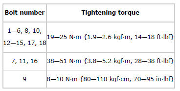
2. Tighten the cylinder head cover installation bolts in the order shown in the figure.
Tightening torque
- 7-10 N*m {71-110 kgf*cm, 62-95 in*lbf}

