Mazda 2: Turn and Lane-Change Signals
The ignition must be switched ON to use the turn and lane-change signals.
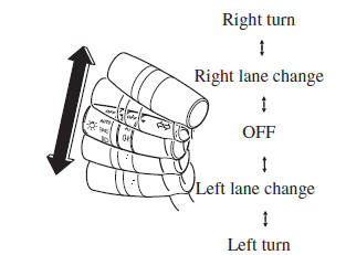
Direction Indicators
Move the signal lever down (for a left turn) or up (for a right turn) to the stop position. The signal will self-cancel after the turn is completed.
If the indicator light continues to fl ash after a turn, manually return the lever to its original position.
The direction indicators (green) in the
instrument cluster fl ash according to the
operation of the direction indicator lever to
show which signal is working. 
NOTE
- If an indicator light stays on without fl ashing or if it fl ashes abnormally, one of the direction indicator bulbs may be burned out.
- A personalised function is available to change the turn indicator sound volume. (page 9-13 )
Lane-Change Signals
Move the lever halfway toward the direction of the lane change—until the indicator fl ashes— and hold it there. It will return to the off position when released.
Three-Flash Turn Signal
To signal a lane change, operate the direction indicator lever up or down slightly and release. After releasing the lever, the direction indicator fl ashes three times.
NOTE
The three-fl ash turn signal function can be switched to operable/inoperable using the personalisation function.
Refer to Personalisation Features on page 9-13 .

