Mazda 2: Blower Motor
BLOWER MOTOR REMOVAL/INSTALLATION
1. Disconnect the negative battery cable.
2. Remove the following parts:
- Rear console (See REAR CONSOLE REMOVAL/INSTALLATION).
- Shift lever knob (MTX) (See MANUAL TRANSAXLE SHIFT MECHANISM REMOVAL/INSTALLATION).
- Side wall (See SIDE WALL REMOVAL/INSTALLATION).
- Front console component (See FRONT CONSOLE COMPONENT REMOVAL/INSTALLATION).
- Front scuff plate (LH) (See FRONT SCUFF PLATE REMOVAL/INSTALLATION).
- Front side trim (LH) (See FRONT SIDE TRIM REMOVAL/INSTALLATION).
- Hood release lever (See HOOD LATCH AND RELEASE LEVER REMOVAL/INSTALLATION).
- Lower panel (driver-side) (See LOWER PANEL REMOVAL/INSTALLATION).
- Knee bolster (See KNEE BOLSTER REMOVAL/INSTALLATION).
3. Remove the wiring harness clip from the brake pedal.
4. Remove the brake pedal installation nuts.
5. Remove the snap pin and clevis pin.
6. Pull the power brake unit from the engine compartment side.
7. Pull the brake pedal outward while lifting it.
CAUTION:
- When removing/installing the blower motor due to a motor rotation malfunction, be careful that the sirocco fan does not interfere with other parts.
8. Remove in the order indicated in the table.
- Connector
- Blower motor
9. Install in the reverse order of removal.
BLOWER MOTOR INSPECTION
1. Connect battery positive voltage to terminal B and ground to terminal A of the blower motor and verify its operation.
- If not as specified, replace the blower motor.
RESISTOR REMOVAL/INSTALLATION
1. Disconnect the negative battery cable.
2. Remove in the order indicated in the table.
- Connector
- Resistor
3. Install in the reverse order of removal.
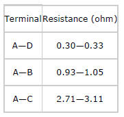
RESISTOR INSPECTION
1. Verify that the resistance between the terminals of the resistor is as shown in the table.
- If not as specified, replace the resistor.