Mazda 2: EPS Control Module
EPS CONTROL MODULE INSPECTION
1. Remove the side wall. (See SIDE WALL REMOVAL/INSTALLATION).
2. Remove the front console component. (See FRONT CONSOLE COMPONENT REMOVAL/INSTALLATION).
3. Remove the front scuff plate (LH) and front side trim (LH). (See FRONT SCUFF PLATE REMOVAL/INSTALLATION). (See FRONT SIDE TRIM REMOVAL/INSTALLATION).
4. Disconnect the hood release lever from the lower panel. (See HOOD LATCH AND RELEASE LEVER REMOVAL/INSTALLATION).
5. Remove the lower panel. (See LOWER PANEL REMOVAL/INSTALLATION).
6. Remove the heat duct (LH). (See HEAT DUCT COMPONENT REMOVAL/INSTALLATION).
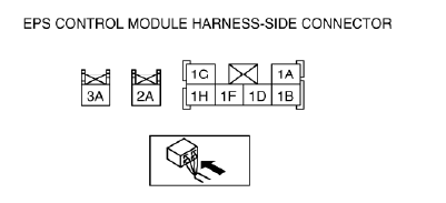
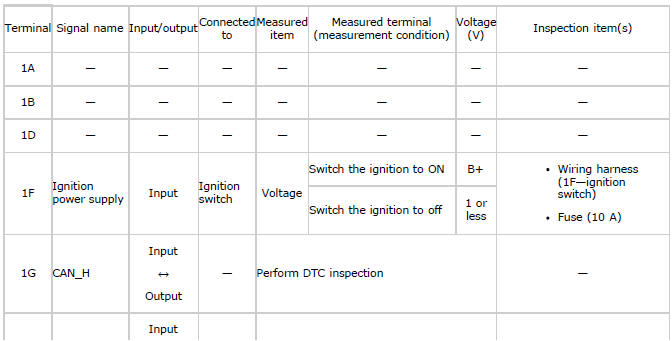
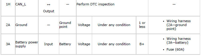
7. Attach the tester lead to the underside of the EPS CM connector and inspect the voltage according to the terminal voltage table (reference).
Terminal Voltage Table (Reference)
EPS CONTROL MODULE CONFIGURATION
CAUTION:
- If the EPS CM configuration is not completed, the EPS will not operate properly. If the steering column (EPS CM) is replaced, always carry out the EPS CM configuration so that the EPS operates properly.
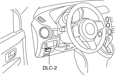
1. Connect the M-MDS (IDS) to the DLC-2.
2. After the vehicle is identified, select the following items from the initial screen of the IDS.
3. Then, select items from the screen menu in the following order.
- Select "Module Programming".
- Select "Programmable Module Installation".
- Select "EPS".
4. Perform the configuration according to the directions on the screen.
5. Retrieve DTCs by the IDS, then verify that there is no DTC present.
- If a DTC (s) is detected, perform the applicable DTC inspection. (See ELECTRIC POWER STEERING (EPS) ON-BOARD DIAGNOSIS).
EPS STEERING ANGLE CALIBRATION
CAUTION:
- If the EPS steering angle calibration is not completed, the EPS will not
operate properly.
If the EPS warning light illuminates or flashes when the engine is started and the steering wheel is turned lock-to-lock after the following procedure, always perform the EPS system steering angle calibration so that the EPS operates properly.
- Steering column (EPS CM) removal/installation
- Intermediate shaft disconnection
1. Connect the M-MDS to the DLC-2.
2. After the vehicle is identified, select the following items from the initialization screen of the M-MDS.
- Select "Chassis".
- Select "EPS Steering Angle Calibration".
3. Then, select "Steering Angle Calibration" from the screen menu.
4. Perform the procedure according to the directions on the screen.
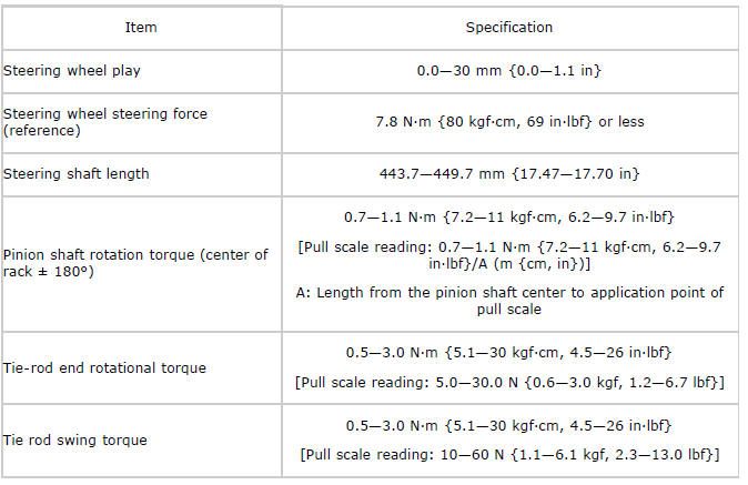
STEERING TECHNICAL DATA
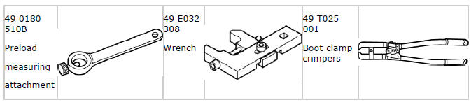
STEERING SST