Mazda 2: Engine Control System Operation Inspection
Main Relay Operation Inspection
1. Verify that the main relay clicks when the ignition switch is turned to the ON position, then off.
- If there is no operation sound, inspect the following:
- Main relay (See RELAY INSPECTION).
- Wiring harness and connector between battery and main relay terminal C
- Wiring harness and connector between PCM terminal 1AJ and main relay terminal B
Intake Manifold Vacuum Inspection
1. Verify the air intake hoses are installed properly.
2. Start the engine and idle it.
3. Disconnect the vacuum hose between the intake manifold and purge solenoid valve from the purge solenoid valve side.
4. Connect a vacuum gauge to the vacuum hose and measure the intake manifold vacuum. (See INTAKE MANIFOLD VACUUM INSPECTION).
- If not as specified, inspect the following:
NOTE:
- Air suction can be located by engine speed change when lubricant is
sprayed on the area where suction is occurring.
- Air suction at throttle body, intake manifold and PCV valve installation points
- Accelerator cable free play
- Fuel injector insulator
- Engine compression (See COMPRESSION INSPECTION).
Drive-by-wire Control System Inspection
Engine coolant temperature compensation inspection
1. Connect the M-MDS to the DLC-2.
2. Access the following PIDs: (See ON-BOARD DIAGNOSTIC TEST).
- ECT1
- IAT
- RPM
3. Verify that the engine is cold, then start the engine.
4. Verify that the engine speed decreases as the engine warms up.
- If the engine speed does not decrease or decreases slowly, inspect the
following:
- ECT sensor No.1 and related wiring harness (See ENGINE COOLANT TEMPERATURE (ECT) SENSOR INSPECTION).
- Throttle body and related wiring harness (See THROTTLE BODY INSPECTION).
Load compensation inspection
1. Start the engine and idle it.
2. Connect the M-MDS to the DLC-2.
3. Verify that P0506:00 or P0507:00 is not displayed. (See ON-BOARD DIAGNOSTIC TEST).
- If P0506:00 or P0507:00 are displayed, perform DTC inspection. (See DTC P0506:00). (See DTC P0507:00).
4. Access the RPM PID. (See ON-BOARD DIAGNOSTIC TEST).
NOTE:
- Excludes temporary idle speed drop just after the loads are turned on.
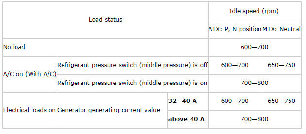
5. Verify that the engine speed is within the specification under each load condition.
- If load condition is not as specified, inspect the following:
- A/C switch and related wiring harness
- Fan switch and related wiring harness
Idle-up speed
Throttle position (TP) sweep inspection
1. Connect the M-MDS to the DLC-2.
2. Switch the ignition to ON.
3. Verify that none of the following DTCs are displayed: (See ON-BOARD DIAGNOSTIC TEST).
- P0122:00, P0123:00, P0222:00, P0223:00, P0638:00, P2101:00, P2107:00,
P2108:00, P2109:00, P2112:00, P2119:00,
P2122:00, P2123:00, P2127:00, P2128:00, P2135:00, P2138:00
- If any one DTC is displayed, perform DTC inspection. (See DTC TABLE).
4. Access the TP REL PID. (See ON-BOARD DIAGNOSTIC TEST).
5. Verify that the PID reading is within the CTP value. (See PCM INSPECTION).
- If the PID reading is out of range, perform the following:
- Remove the air duct from the throttle body.
- Verify that the throttle valve opens when the accelerator pedal is
depressed.
- If the throttle valve opens, inspect the TP sensor and related wiring harness.
- If the throttle valve does not open, inspect the throttle valve actuator control motor and related wiring harness.
6. Gradually depress the throttle pedal and verify that the PID reading increases accordingly.
- If the PID reading drops momentarily, inspect the following:
- TP sensor
7. Fully depress the throttle pedal and verify that the PID reading is within WOT value. (See PCM INSPECTION).
- If the PID reading is out of range, perform the followings:
- Remove the air duct from throttle body.
- Verify that the throttle valve opens when throttle pedal is
depressed.
- If the throttle valve opens, inspect the TP sensor and related wiring harness.
- If the throttle valve does not open, inspect the throttle valve actuator control motor and related wiring harness.
Brake override system operation inspection
NOTE:
- If the brake override system operates normally after performing the following inspection, the PCM detects DTC P2299:00.
1. Start the engine and idle it.
2. Verify that the engine speed is below 1,100 rpm while the all of the following conditions are met.
- Neutral (MTX)
- P, or N position (ATX)
- Engine speed is above 1,150 rpm while not idling.
- Brake pedal is depressed.
- If the engine speed is below 1,100 rpm, clear the PCM DTC using the M-MDS. (System operation is normal).
- If the engine speed is not below 1,100 rpm, inspect the following:
- APP sensor
(See ACCELERATOR PEDAL POSITION (APP) SENSOR INSPECTION). - Neutral switch (MTX)
(See NEUTRAL SWITCH INSPECTION). - Clutch switch (MTX)
(See CLUTCH PEDAL POSITION (CPP) SWITCH INSPECTION). - TR switch (ATX)
(See TRANSAXLE RANGE (TR) SWITCH INSPECTION). - Brake switch No.1
(See BRAKE SWITCH INSPECTION [ATX] ).
(See BRAKE SWITCH INSPECTION [MTX] ). - Brake switch No.2
(See BRAKE SWITCH INSPECTION [ATX] ).
(See BRAKE SWITCH INSPECTION [MTX] ). - Communication between PCM and TCM (ATX)
(See FOREWORD [MULTIPLEX COMMUNICATION SYSTEM] ).
- APP sensor
Variable Tumble Control Operation Inspection
1. Connect the M-MDS to the DLC-2.
2. Perform the KOEO self test using M-MDS. (See KOEO/KOER SELF TEST).
3. Verify that DTC P2004:00, DTC P2006:00 and DTC P2008:00 are not displayed.
- If DTC P2004:00, DTC P2006:00 or DTC P2008:00 is shown, perform the DTC
inspection. (See DTC P2004:00).
(See DTC P2006:00). (See DTC P2008:00).
4. Switch the ignition to ON (engine off).
5. Monitor ECT1, RPM and IMRC PIDs. (See ON-BOARD DIAGNOSTIC TEST).
6. Verify that ECT1 PID is 60

