Mazda 2: Drive Belt
DRIVE BELT INSPECTION
NOTE:
- Drive belt deflection/tension inspection is not necessary because of the use of the drive belt auto tensioner.
1. Remove the splash shield (RH).
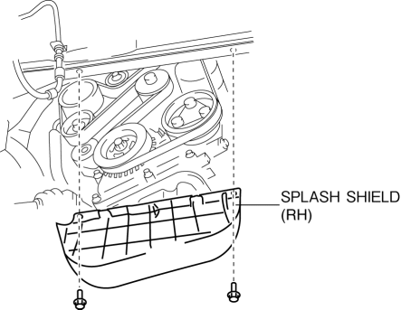
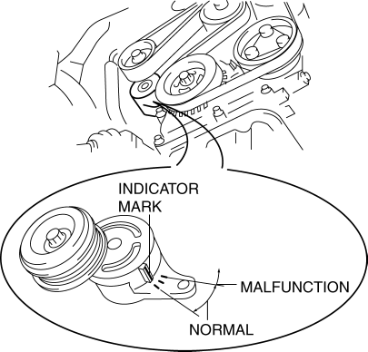
2. Verify that the drive belt auto tensioner indicator mark does not exceed the limit.
- If it exceeds the limit, replace the drive belt. (See DRIVE BELT REMOVAL/INSTALLATION).
3. Visually inspect the drive belt.
- If any of the following damage occurs to the drive belt, replace the
drive belt. (See DRIVE BELT REMOVAL/INSTALLATION).
- Cracks
- Foreign material caught in mechanism
- Belt loss
4. Install the splash shield (RH).
Tightening torque
- 8-10 N*m {80-109 kgf*cm, 70-94 in*lbf}
DRIVE BELT REMOVAL/INSTALLATION
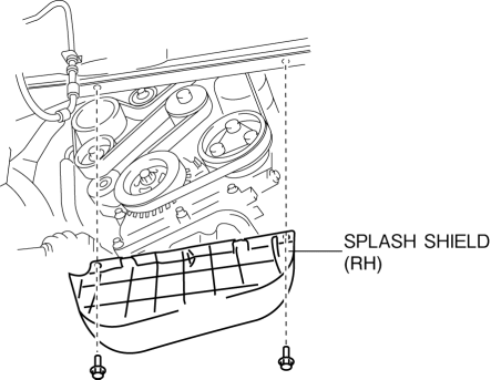
1. Remove the splash shield (RH).
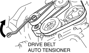
2. Rotate the drive belt auto tensioner in the direction shown in the figure and remove the drive belt.
3. Install the drive belt.
4. Verify that the drive belt auto tensioner indicator mark does not exceed the limit. (See DRIVE BELT INSPECTION).
5. Install the splash shield (RH).
Tightening torque
- 8-10 N*m {80-109 kgf*cm, 70-94 in*lbf}
DRIVE BELT AUTO TENSIONER INSPECTION
1. Remove the drive belt. (See DRIVE BELT REMOVAL/INSTALLATION).
2. Verify that the drive belt auto tensioner moves smoothly in the operational direction.
- If it does not move smoothly, replace the drive belt auto tensioner. (See TIMING CHAIN REMOVAL/INSTALLATION).
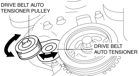
3. Rotate the drive belt auto tensioner pulley by hand and verify that it rotates smoothly.
- If it does not move smoothly, replace the drive belt auto tensioner. (See TIMING CHAIN REMOVAL/INSTALLATION).
4. Install the drive belt. (See DRIVE BELT REMOVAL/INSTALLATION).

