Mazda 2: M-MDS and Vehicle Not Communicating [Multiplex Communication System]
Mazda 2 2007-2014 Service Manual / Body and Accessories / M-MDS and Vehicle Not Communicating [Multiplex Communication System]
CAUTION:
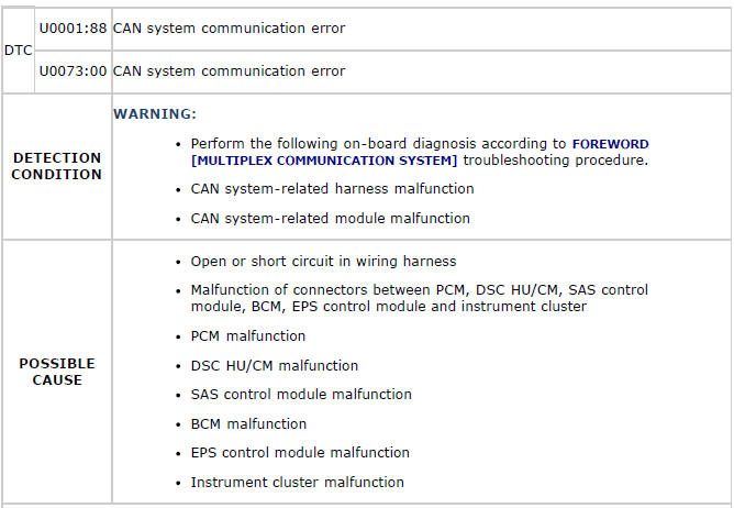
- Perform the following on-board diagnosis according to FOREWORD [MULTIPLEX COMMUNICATION SYSTEM] troubleshooting procedure.
Detection Condition
- Possible causes of communication errors between the M-MDS and vehicle include communication circuit interruption due to an open circuit in the CAN communication wiring harness, or poor contact of connector terminals, or a BUS OFF condition due to a short circuit in the CAN communication wiring harness.
Possible Causes
- Open circuit in wiring harness between PCM and DLC-2
- Open circuit in BCM CAN line
- Improper insertion, connector terminal damage, deformation, corrosion, or disconnection of PCM, BCM, or connector C-03
- Short circuit in wiring harness between CAN system-related module CAN_L and CAN_H lines
- Short circuit to power supply in wiring harness between CAN system-related module
- Short circuit to ground in wiring harness between CAN system-related module
- Short circuit to power supply in CAN system-related module internal CAN lines
- Short circuit to ground in CAN system-related module internal CAN lines
- Damage, deformation, corrosion, or disconnection of DLC-2
- PCM power supply is not normal
- PCM ground is not normal
- PCM internal resistance is not normal
- CAN system-related module malfunction
Wiring Diagram
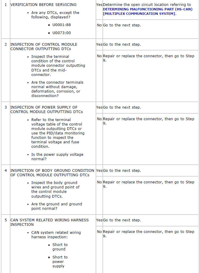
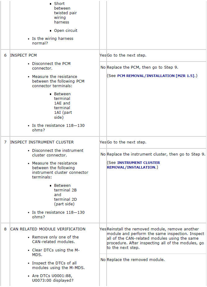
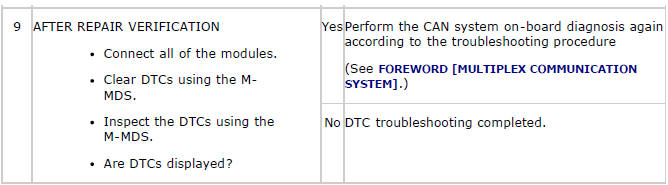
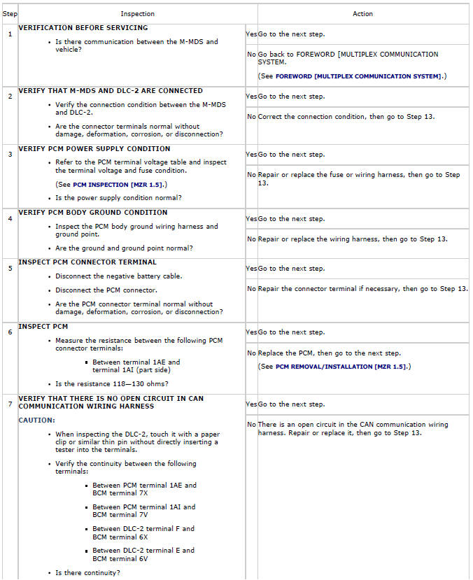
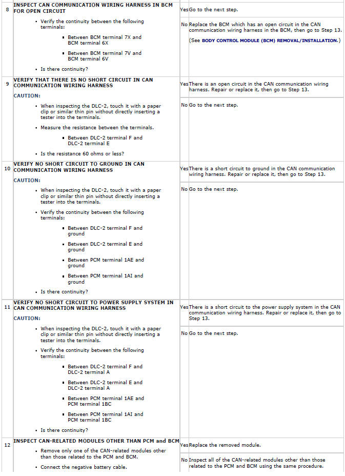
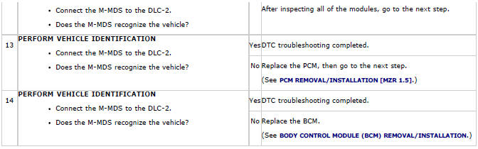
Diagnostic Procedure
CAUTION:
- When disconnecting the connector, verify that there is no looseness, damage, deformation, corrosion, or poor connection of the connector terminals.
DTC U0001:88, U0073:00
Diagnostic procedure
CAUTION:
- When disconnecting the connector, verify that there is no looseness, damage, deformation, corrosion, or poor connection of the connector terminals.