Mazda 2: ON-Board Diagnostic Wiring Diagram [Instrument Cluster]
DTC INSPECTION [Instrument Cluster]
1. Connect the M-MDS (IDS) to the DLC-2.
2. After the vehicle is identified, select the following items from the initialization screen of the IDS.
- Select "Self Test".
- Select "Modules".
- Select "IC".
3. Verify the DTC according to the directions on the screen.
- If any DTCs are displayed, perform troubleshooting according to the corresponding DTC inspection.
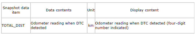
Snapshot data table
NOTE:
- Snapshot data items are not displayed, according to detected DTC.
4. After completion of repairs, clear all DTCs stored in the instrument cluster. (See CLEARING DTC [INSTRUMENT CLUSTER] ).
CLEARING DTC [Instrument Cluster]
1. Connect the M-MDS (IDS) to the DLC-2.
2. After the vehicle is identified, select the following items from the initialization screen of the IDS.
- Select "Self Test".
- Select "Modules".
- Select "IC".
3. Verify the DTC according to the directions on the screen.
4. Press the clear button on the DTC screen to clear the DTC.
5. Switch the ignition to off.
6. Switch the ignition to ON and wait for 5 s or more.
7. Perform DTC inspection. (See DTC INSPECTION [INSTRUMENT CLUSTER] ).
8. Verify that no DTCs are displayed.

