Mazda 2: OBD-II Drive Mode
- Using the OBD-II Drive Mode, the monitoring item requested by OBD-II regulations can be easily diagnosed.
- Performing the Drive Mode inspects the OBD-II system for proper operation and must be performed to ensure that no additional DTCs are present.
- The OBD-II Drive Mode is divided into the specific Drive Mode and single Drive Mode.
- For the specific Drive Mode, specified Drive Modes have been set for each individual monitoring item requested by OBD-II regulations, and they can be diagnosed individually. For the single Drive Mode, the entire monitoring item requested by OBD-II regulations can be diagnosed.
- The following modes are in the specific Drive Mode. The applicable
system is diagnosed by driving in the following Drive Modes.
- Mode 03 (EGR System, A/F Sensor Heater, HO2S Heater, A/F Sensor, HO2S and TWC Repair Verification Drive Mode)
- Mode 06 (EVAP System Repair Verification Drive Mode)
- The following systems are diagnosed with the single Drive Mode.
- EGR system
- Oxygen sensor (A/F sensor, HO2S)
- Oxygen sensor heater (A/F sensor heater, HO2S heater)
- Catalytic converter (TWC)
- Evaporative (EVAP) system
- OCV (variable valve timing control)
CAUTION:
- While performing the Drive Mode, always operate the vehicle in a safe and lawful manner.
- When the M-MDS is used to observe monitor system status while driving, be sure to have another technician with you, or record the data in the M-MDS using the PID/DATA MONITOR AND RECORD function and inspect later.
NOTE:
- Vehicle speed and engine speed detected by the PCM may differ from that indicated by the speedometer and tachometer. Use the M-MDS to monitor vehicle speed.
- If the OBD-II system inspection is not completed during the Drive Mode,
the following causes are considered:
- The OBD-II system detects the malfunction.
- The Drive Mode procedure is not completed correctly.
- Disconnecting the battery will reset the memory. Do not disconnect the battery during and after Drive Mode.
- The M-MDS can be used at anytime through the course of the Drive Mode to monitor the completion status. Monitoring can be done by viewing the ON BOARD SYSTEM READINESS menu.
- The OBD monitoring status can be confirmed with the ignition switch
operation. During KOEO, the MIL illuminates for a fail-light
inspection for approx. 17 s. The OBD monitoring status is confirmed after
the fail-light inspection.
- If all of the diagnosis is completed even one time, the MIL will continue to illuminate.
- If all of the diagnosis is not completed, the MIL flashes for approx. 7 s, and then it illuminates until the engine is started.
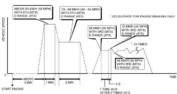
Mode 03 (EGR System, A/F Sensor Heater, HO2S Heater, A/F Sensor, HO2S and TWC Repair Verification Drive Mode)
1. Start the engine and warm it up completely.
2. Verify all accessory loads (A/C, headlights, blower fan, rear window defroster) are off.
3. Drive the vehicle as shown in the graph. The driving conditions before driving at constant speed are not specified.
4. Stop the vehicle and access the ON BOARD SYSTEM READINESS menu of GENERIC OBD-II FUNCTION to verify the OBD monitoring status.
- If completed, the OBD monitoring status items change from non-completed to completed.
- If not completed, switch the ignition to off then repeat from Step 4.
5. Access the DIAGNOSTIC MONITORING TEST RESULTS menu of GENERIC OBD-II FUNCTIONS to verify the monitor results.
- If detected values are not within the specification, repair has not been completed.
6. Verify no DTCs are available.
Mode 06 (EVAP System Repair Verification Drive Mode)
NOTE:
- If "EVAP System Repair Verification Drive Mode" cannot be performed (it is impossible to drive the vehicle under this Drive Mode condition), perform evaporative system test procedure as an alternative. (See ENGINE CONTROL SYSTEM OPERATION INSPECTION).
1. Verify that all of the following PIDs are within the following specifications. All PIDs must be within specifications before engine is started to initiate the evaporative system test.
- BARO: 72.2 kPa {542 mmHg, 21.3 inHg} or higher
- FLI: 15-85 %
- IAT: 5-35

