Mazda 2: Positive Crankcase Ventilation (PCV)
POSITIVE CRANKCASE VENTILATION (PCV) VALVE REMOVAL/INSTALLATION
1. Disconnect the negative battery cable. (See BATTERY REMOVAL/INSTALLATION).
2. Remove the fresh-air duct and the air cleaner as a single unit. (See INTAKE-AIR SYSTEM REMOVAL/INSTALLATION).
3. Remove the intake manifold and the fuel distributor component as a single unit. (See INTAKE-AIR SYSTEM REMOVAL/INSTALLATION).
4. Disconnect the PCV hose from the PCV valve.
5. Remove the oil level gauge pipe. (See TIMING CHAIN REMOVAL/INSTALLATION).
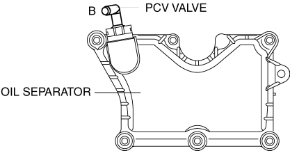
6. Remove the PCV valve and the oil separator as a single unit.
7. Install in the reverse order of removal.
Oil separator tightening torque
- 8-10 N*m {82-101 kgf*cm, 71-88 in*lbf}
POSITIVE CRANKCASE VENTILATION (PCV) VALVE INSPECTION
Airflow Inspection
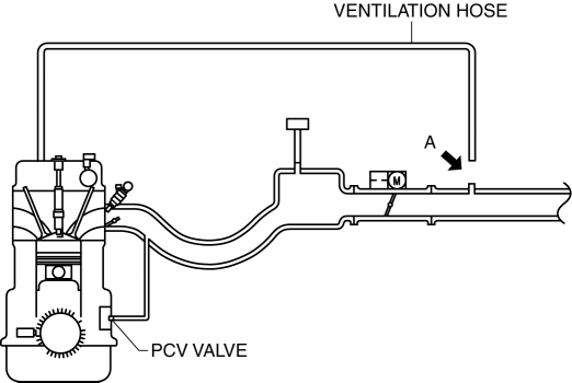
1. Disconnect the section (A) of the ventilation hose shown in the figure.

2. Start the engine and verify that vacuum is applied to the end of the disconnected ventilation hose while the engine is idling.
- If vacuum does not occur in the ventilation hose, perform the procedure from Step 3.
NOTE:
- If the PCV valve is operating normally, vacuum occurs in the ventilation hose, however, if there is a malfunction in the PCV valve, positive pressure occurs in the ventilation hose because the blow-by gas is circulated to the air hose from the ventilation hose.
- Verify the ventilation hose vacuum using the following methods:
- When the tip of your finger touches the end of the ventilation hose, it is suctioned by the hose.
- When a thin scrap of paper contacts the end of the ventilation hose, it is suctioned by the hose.
3. Disconnect the negative battery cable. (See BATTERY REMOVAL/INSTALLATION).
4. Remove the fresh-air duct and the air cleaner as a single unit. (See INTAKE-AIR SYSTEM REMOVAL/INSTALLATION).
5. Remove the intake manifold and the fuel distributor component as a single unit. (See INTAKE-AIR SYSTEM REMOVAL/INSTALLATION).
6. Disconnect the PCV hose from the PCV valve.
7. Remove the oil level gauge pipe. (See TIMING CHAIN REMOVAL/INSTALLATION).
8. Remove the PCV valve and the oil separator as a single unit.
9. Verify that there is no airflow when pressure is applied to port B.

- If there is airflow, replace the PCV valve and the oil separator as a single unit. (See POSITIVE CRANKCASE VENTILATION (PCV) VALVE REMOVAL/INSTALLATION).
10. Verify that there is airflow when vacuum is applied to port B.
- If there is no airflow, replace the PCV valve and the oil separator as a single unit. (See POSITIVE CRANKCASE VENTILATION (PCV) VALVE REMOVAL/INSTALLATION).
WARM-UP THREE-WAY CATALYTIC CONVERTER (WU-TWC) INSPECTION
CAUTION:
- Perform the following procedures, DTC P0421:00 is indicated only.
1. Connect the M-MDS to the DLC-2.
2. Start the engine and warm it up to normal operating temperature.
3. Turn off the engine.
4. Verify that the engine compression is within the specification. (See COMPRESSION INSPECTION).
- If the compression pressure is not within the specification, repair or replace the malfunctioning part.
5. Drive the vehicle for 10 min at 65-96 km/h {40-60 mph} to allow the WU-TWC to reach normal operating temperature.
6. Stop the vehicle and leave it in a safe space.
7. Access Test ID 10:21:80 on the "Diagnostic Monitoring Test Result" function.
8. Verify that the test result is within specification indicated on the M-MDS.
- If it is not as specified, replace the WU-TWC. (See EXHAUST SYSTEM REMOVAL/INSTALLATION).
ROLLOVER VALVE REMOVAL/INSTALLATION
NOTE:
- The rollover valve cannot be removed as it is built into the fuel tank.
ROLLOVER VALVE INSPECTION
NOTE:
- The rollover valve cannot be disassembled and inspected as it is built into the fuel tank.
1. Perform the fuel tank inspection. (See FUEL TANK INSPECTION).
- If malfunction, replace the fuel tank. (See FUEL TANK REMOVAL/INSTALLATION).

