Mazda 2: Wheel Unit ID Registration
NOTE:
- After the wheel unit replacement, registration of the wheel unit identification codes must be performed.
- ID registration can be done using the M-MDS, or not using the M-MDS.
Using M-MDS
1. Connect the M-MDS (IDS) to DLC-2.
2. After the vehicle is identified, select the following items from the initialization screen of the IDS.
- Select the "Body".
- Select the "TPMS Functions".
- Select the "Wheel Unit ID Registration".
3. Select an item from the screen menu.
- Wheel unit ID registration: WU ID Registration
- Monitoring wheel unit ID: Monitor WU ID Registration
4. Leave the vehicle with the ignition to off for 15 min or more.
5. Switch the ignition to ON (engine ON).
6. Verify that the TPMS warning light turns on and off in 0.5 s cycles repeatedly.
7. Drive the vehicle at a speed of 25 km/h {15.5 mph} or more for 10 min to implement the wheel unit ID registration.
NOTE:
- If the ID registration is not completed even after driving the vehicle for 10 min or more at a speed of 25 km/h {15.5 mph} or more, the TPMS warning light flashes.
8. Verify that the TPMS warning light turns off.
NOTE:
- If the wheel unit ID registration cannot be performed after driving 10 min or more, refer to the symptom troubleshooting procedure.
Without Using M-MDS
1. Switch the ignition to the ON, then switch it to off.
2. Leave the vehicle with the engine off for 15 min or more.
3. Drive the vehicle at a speed of 25 km/h {15.5 mph} or more for 10 min or more.
4. After driving for 10 min, verify that the TPMS warning light does not flash and is not illuminated.
WHEEL UNIT REMOVAL/INSTALLATION
1. Remove in the order indicated in the table.
2. Install in the reverse order of removal.
3. Install the valve core and valve cap, put air into the tire.
CAUTION:
- A TPMS wheel unit has an exclusive valve cap and valve core. If a valve core other than the exclusive one is installed, the wheel unit could be damaged due to the generation of rust. Always install the exclusive valve cap and valve core for TPMS.
- The wheel unit air pressure stem is made from aluminum and can be damaged. Do not tilt or use excessive side force when checking air pressure or filling tire with air. Some tire pressure gauges and air filling nozzles have extended tips, which can provide enough leverage to easily bend or break the wheel unit.
4. When replacing wheel unit (s), register the new wheel unit ID (s). (See WHEEL UNIT ID REGISTRATION).
NOTE:
- If the wheel unit is replaced with a new one, the ID registration must
be performed.
When the ID registration is finished, the data for the new wheel unit is displayed on the M-MDS.
- Valve cap
- Valve core
- Tire
- Valve nut
- Wheel unit component
- Seal
- Wheel unit
Valve Core Removal Note
1. Remove the valve core of the wheel unit, and bleed the air from the tire.
Tire Removal Note
1. Set the bead breaker at the position laterally opposed to the valve.
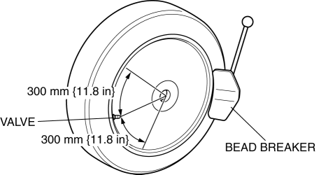
2. Break the bead loose.
CAUTION:
- Do not break the bead loose within the range of 300 mm {11.8 in} on each side of the valve. Otherwise, the wheel unit could be damaged.
3. Break the bead loose on the other side of the wheel.
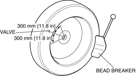
CAUTION:
- Set the bead breaker at the position laterally opposed to the valve.
- Do not break the bead loose within the range of 300 mm {11.8 in} on each side of the valve. Otherwise, the wheel unit could be damaged.
4. Insert the tire lever at the point 40 mm {1.6 in} from the wheel unit in the direction that the tire changer turntable rotates.
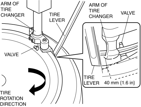
5. Remove the bead from the wheel.
NOTE:
- Using the tire lever as a support will aid in preventing the tire changer arm from deviating from the point at which the bead is first broken.
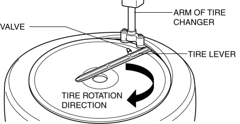
6. For the other side, insert the tire lever at the point of 40 mm {1.6 in} from the wheel unit in the direction that the tire changer turntable rotates, and remove the bead from the wheel.
Tire Installation Note
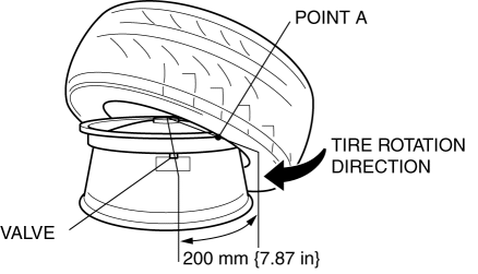
1. Set the tire at the point A (200 mm {7.87 in} away from the valve hole), and install the tire.
2. Set the tire at the point A (200 mm {7.87 in} away from the valve hole).
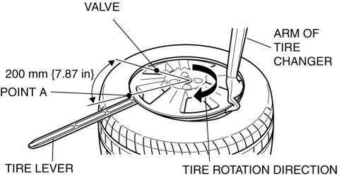
NOTE:
- Using the tire lever as a support will aid in preventing the tire from deviating from the point A.
3. Install the tire.
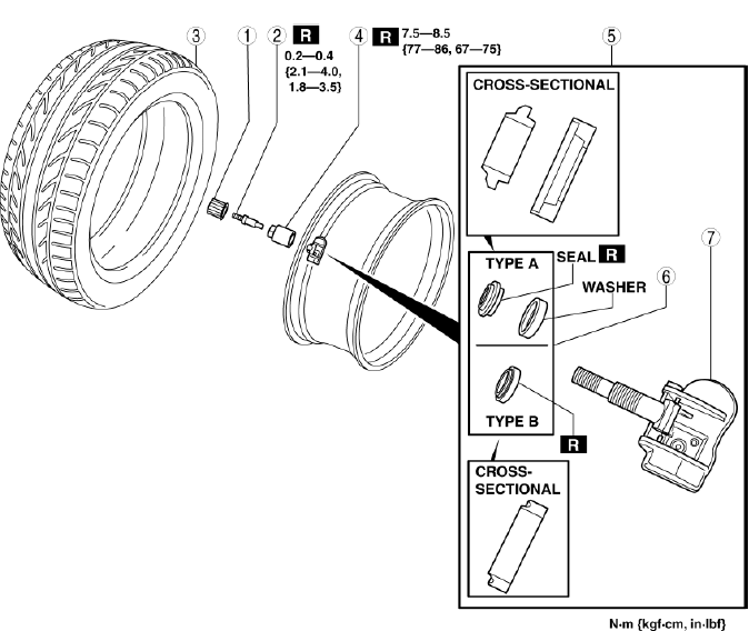
Wheel Unit Component Installation Note
1. Insert the valve into the wheel unit in the order shown in the figure.
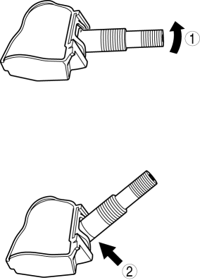
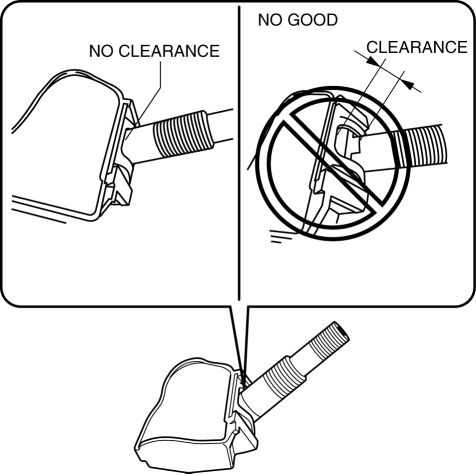
2. Verify that the valve is installed into the wheel unit completely as shown in the figure.
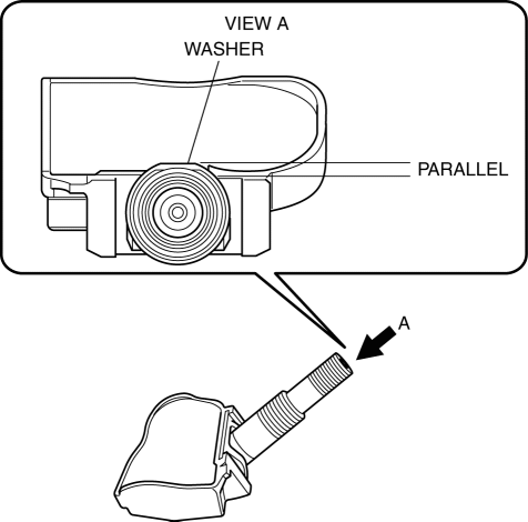
3. Install the washer and new seal (type A) or the seal (type B).
4. If the wheel unit is equipped with the seal and washer (type A), verify that the washer is Installed to the valve as shown in the figure.
5. Insert the wheel unit valve into the valve hole so that the polyurethane foam side faces the wheel.
6. Temporarily tighten the valve nut by hand.
7. Completely tighten the valve nut using a torque wrench.
Tightening torque
- 7.5-8.5 N*m {77-86 kgf*cm, 67-75 in*lbf}
CAUTION:
- Do not retighten the valve nut after the initial operation.
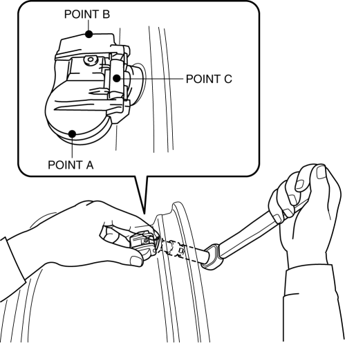
NOTE:
- Hold the end of the wheel unit (POINTs A and B) with your thumb and middle fingers so that the wheel unit does not rotate, and then hold the valve (POINT C) with your index finger so that the valve does not detach from the wheel unit.
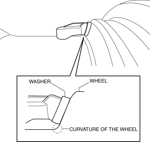
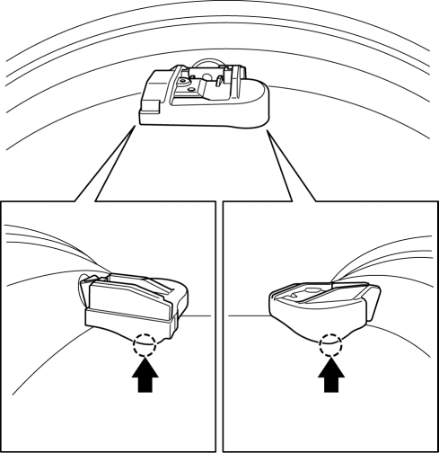
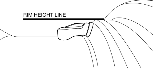
8. Verify that the wheel unit component is correctly installed.
- Both ends or one end of the wheel unit contacts the wheel as shown in the figure.
- The wheel unit does not exceed the rim height as shown in the figure.
- If the wheel unit is equipped with the seal and washer (type A), verify that the washer does not contact the curvature of the wheel as shown in the figure.