Mazda 2: Front Suspension
FRONT SUSPENSION LOCATION INDEX
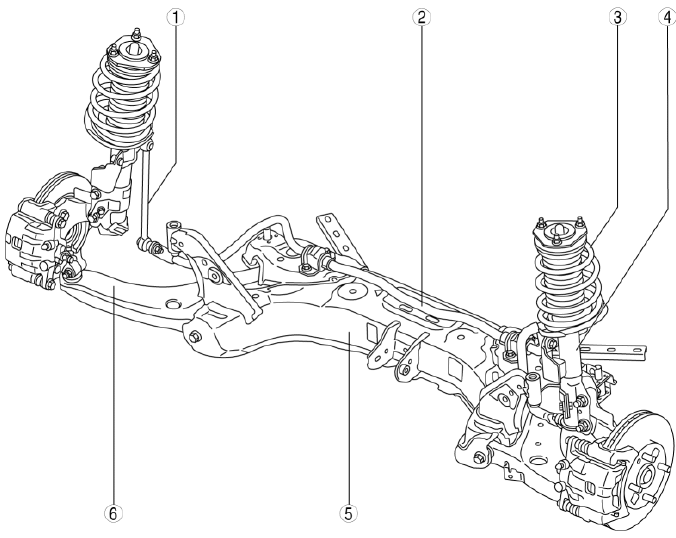
- Stabilizer control link
- (See FRONT STABILIZER CONTROL LINK INSPECTION.)
- Front stabilizer
- (See FRONT STABILIZER REMOVAL/INSTALLATION.)
- Front shock absorber and coil spring
- (See FRONT SHOCK ABSORBER AND COIL SPRING REMOVAL/INSTALLATION.)
- (See FRONT SHOCK ABSORBER AND COIL SPRING DISASSEMBLY/ASSEMBLY.)
- Front shock absorber
- (See FRONT SHOCK ABSORBER INSPECTION.)
- (See FRONT SHOCK ABSORBER DISPOSAL.)
- Front crossmember
- (See FRONT CROSSMEMBER REMOVAL/INSTALLATION.)
- Front lower arm
- (See FRONT LOWER ARM REMOVAL/INSTALLATION.)
- (See FRONT LOWER ARM INSPECTION.)
FRONT SHOCK ABSORBER AND COIL SPRING REMOVAL/INSTALLATION
1. Remove in the order indicated in the table.
2. Install in the reverse order of removal.
3. Inspect the wheel alignment and adjust it if necessary. (See FRONT WHEEL ALIGNMENT).
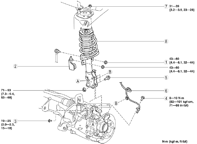
- Nut (stabilizer control link upper end)
- Dynamic damper
- Bolt (brake hose bracket)
- Bolt (ABS wheel-speed sensor)
- Bolt (lower end of shock absorber)
- ABS wheel-speed sensor
- Nut (upper end of shock absorber)
- Shock absorber and coil spring
Bolt (ABS Wheel-Speed Sensor) Removal Note
1. Remove the ABS wheel-speed sensor installation bolt, then remove the ABS wheel-speed sensor from the steering knuckle.
ABS Wheel-Speed Sensor Removal Note
1. Disconnect the steering knuckle from the shock absorber.
2. While pressing the tabs (2 locations) of the ABS wheel-speed wiring harness sensor clip, remove the ABS wheel-speed sensor wiring harness from the shock absorber.
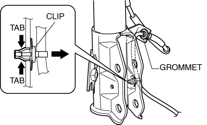
3. Remove the ABS wheel-speed sensor wiring harness grommet from the shock absorber.
4. Move the ABS wheel-speed sensor to a place out of the way.
ABS Wheel-Speed Sensor, Bolt (Lower End Of Shock Absorber), Bolt (ABS Wheel-Speed Sensor) Installation Note
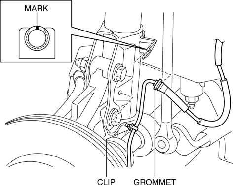
1. Install the steering knuckle to the shock absorber, insert the bolts from the direction shown as follows, then tighten them to the specified torque.
- Vehicle left side: Insert the bolts from the vehicle rear.
- Vehicle right side: Insert the bolts from the vehicle front.
2. Install the ABS wheel-speed sensor wiring harness grommet to the shock absorber as shown in the figure.
3. Install the ABS wheel-speed sensor wiring harness clip to the shock absorber.
4. Install the ABS wheel-speed sensor to the steering knuckle, then tighten the bolt (ABS wheel-speed sensor) to the specified torque.
5. Verify that the ABS wheel-speed sensor wiring harness is not twisted.
FRONT SHOCK ABSORBER AND COIL SPRING DISASSEMBLY/ASSEMBLY
1. Remove the front shock absorber and coil spring. (See FRONT SHOCK ABSORBER AND COIL SPRING REMOVAL/INSTALLATION).
2. Disassemble in the order indicated in the table.
3. Assemble in the reverse order of removal.
4. Inspect the wheel alignment and adjust it if necessary. (See FRONT WHEEL ALIGNMENT).
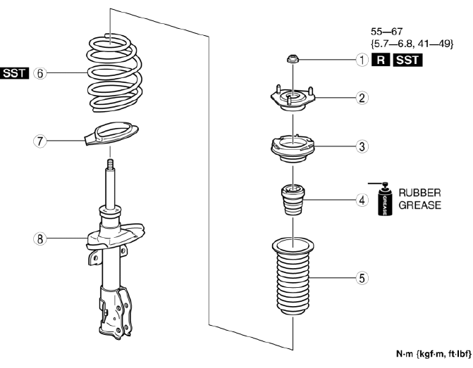
- Piston rod nut
- Mounting rubber
- Bearing
- Bound stopper
- Dust boot
- Coil spring
- Lower spring seat
- Front shock absorber
Piston Rod Nut Disassembly Note
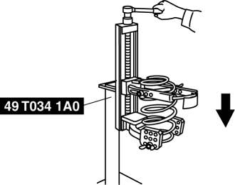
WARNING:
- Before removing the piston rod nut, set the shock absorber and coil
spring to the SST.
Otherwise, the coil spring could fly off under high pressure and cause serious injury or death, or damage to vehicle parts.
1. Install the coil spring to the SST using the following procedure.
NOTE:
- Install the SST using a piece of clean rag to prevent the coil spring from being scratched.
- Set the SST attachments (tabs) to the positions shown in the figure.
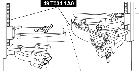
- Install the front shock absorber and coil spring to the SST so that the coil spring is set to the position shown in the figure.
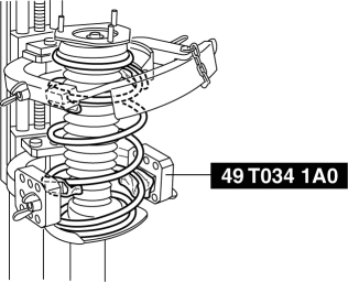
2. Compress the coil spring using the SST.
3. Remove the piston rod nut using the following tools.
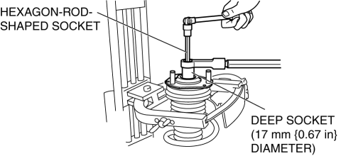
- Deep socket of approx. 17 mm {0.67 in} diameter (hexagon head)
- Hexagon-rod-shaped socket
NOTE:
- Removing the piston rod nut also can be performed by the following tools.
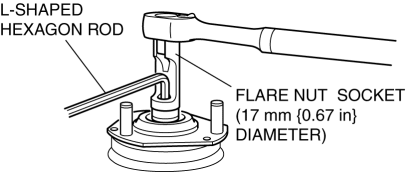
- Flare nut socket of 17 mm {0.67 in} diameter
- L-shaped hexagon rod
Coil Spring Assembly Note
1. Compress the coil spring using the SST.
2. Install the shock absorber with the lower end of the coil spring seated on the step of the lower spring seat.
Bound Stopper Assembly Note
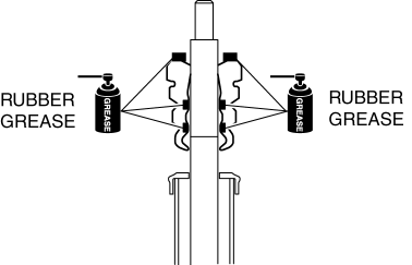
1. Apply the rubber grease to the contact surface of the bound stopper and bearing, and the inside of the bound stopper indicated in the figure.
Mounting Rubber Assembly Note
1. Align the bolt heads of the mounting rubber stud bolt with the hollows in the upper spring seat, and assemble.
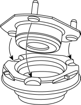
2. Install the mounting rubber so that the angle of the mounting rubber stud and the center of the shock absorber bracket is 60

