Mazda 2: Quick Release Connector (Emission System)
QUICK RELEASE CONNECTOR (EMISSION SYSTEM) REMOVAL/INSTALLATION
CAUTION:
- Disconnecting/connecting the quick release connector without cleaning it may cause damage to the evaporative pipe and quick release connector. Always clean the quick release connector joint area before disconnecting/connecting using a cloth or soft brush, and make sure that it is free of foreign material.
Quick Release Connector Type
CAUTION:
- Verify the type and location, and install/remove properly.
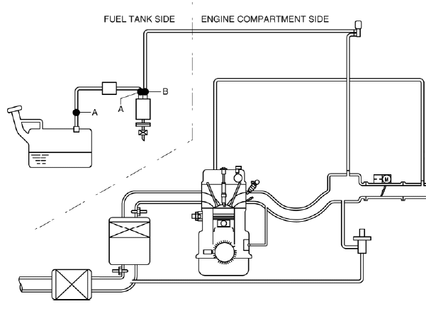
Type A Removal
CAUTION:
- Be careful not to damage the pipe when unlocking the retainer.
NOTE:
- When removing the quick release connector, either SST 49 E042 001 or 49 N013 103A (Part of 49 N013 1A0D) can be used.
When using SST 49 E042 001
NOTE:
- If the quick release connector is removed, replace the retainer with a new one.
1. Set the SST parallel to the quick release connector.
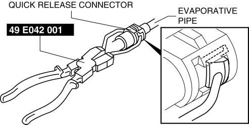
NOTE:
- The quick release connector can be removed by pushing the center of the retainer tabs.
- The retainer is attached to the pipe even after the connector is disconnected.
2. Hold the center of the retainer tabs with the SST ends and press the retainer.
3. Pull the connector side and disconnect the quick release connector.
4. Raise a retainer tab using the SST and remove the retainer.
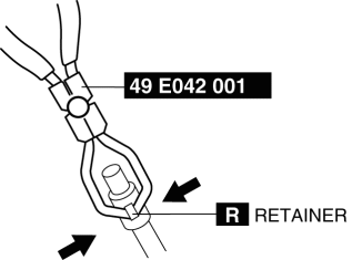
5. Cover the disconnected quick release connector and evaporative pipe with vinyl sheeting or a similar material to prevent it from getting scratched or dirty.
When using SST 49 N013 103A (Part of 49 N013 1A0D)
1. Insert the SST into the quick release connector.
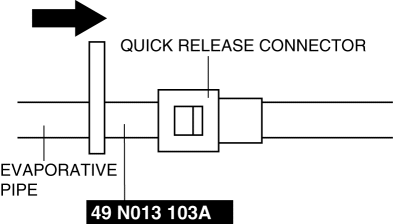
2. Pull the evaporative hose straight out from the evaporative pipe and disconnect it.
3. Cover the disconnected quick release connector and evaporative pipe with vinyl sheeting or a similar material to prevent it from getting scratched or dirty.
Type B Removal
1. Move the retainer upward using a small flathead screwdriver or a similar tool.
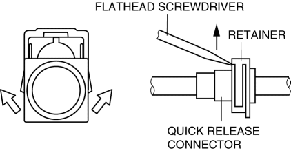
2. Pull out the evaporative hose straight from the evaporative pipe and disconnect it.
3. Cover the disconnected quick release connector and evaporative pipe with vinyl sheeting or a similar material to prevent it from getting scratched or dirty.
Type A Installation
CAUTION:
- Be sure to replace the retainer with a new one to prevent gas leakage.
- To prevent evaporative gas leakage, be sure not to damage the connecting part between the charcoal canister and pipe, and the locks between the quick release connector and retainer. If any of them are damaged, replace the charcoal canister or hose with a new one.
NOTE:
- If the quick release connector O-ring is damaged or has slipped, replace the evaporative hose.
- A checker tab is integrated with the quick release connector for new evaporative hoses. Remove the checker tab from the quick release connector after the connector is completely engaged with the evaporative pipe.
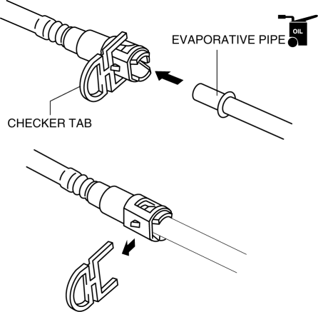
1. Inspect the evaporative hose and evaporative pipe sealing surface for damage and deformation.
- If there is any malfunction, replace it with a new one.
2. Apply a small amount of clean engine oil to the sealing surface of the evaporative pipe.
3. Install a new retainer to the quick release connector.
4. Reconnect the hose straight to the pipe until a click is heard.
5. Lightly pull and push the quick release connector a few times by hand, and then verify that it is connected securely.
Type B Installation
NOTE:
- If the quick release connector O-ring is damaged or has slipped, replace the evaporative hose.
1. Inspect the evaporative hose and evaporative pipe sealing surface for damage and deformation.
- If there is any malfunction, replace it with a new one.
2. Install the quick release connector.
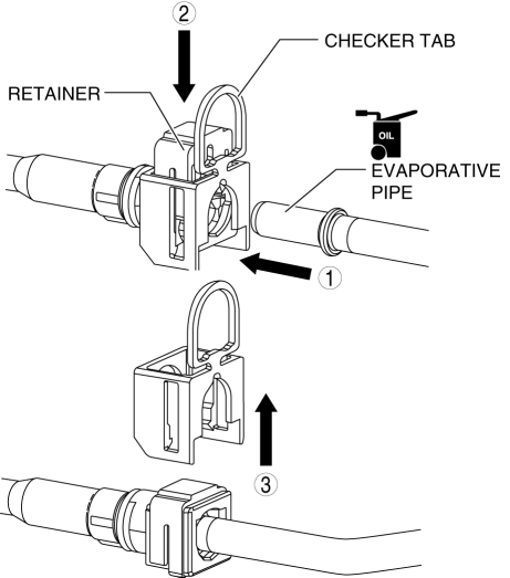
- Insert the evaporative pipe straight to the end of the quick release connector.
- Push down the retainer using a finger.
- If the retainer cannot be pushed down, push the evaporative pipe further to the quick release connector.
3. Lightly pull and push the quick release connector a few times by hand, and then verify that it is connected securely.

