Mazda 2: Power System
POWER SYSTEM LOCATION INDEX
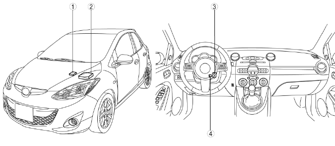
- Main fuse
- Relay
- Ignition switch
- Key reminder switch
FUSE SERVICE CAUTIONS
CAUTION:
- If a fuse is burnt out, inspect the cause and repair the malfunctioning part, then replace the fuse with the specified value. If the fuse is replaced before doing this, it could burn again.
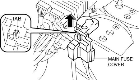
MAIN FUSE REMOVAL/INSTALLATION
1. Disconnect the negative battery cable.
2. Remove the main fuse cover in the direction of the arrow while pressing the tab indicated in the figure.
3. Remove nuts A, B, and C shown in the figure.
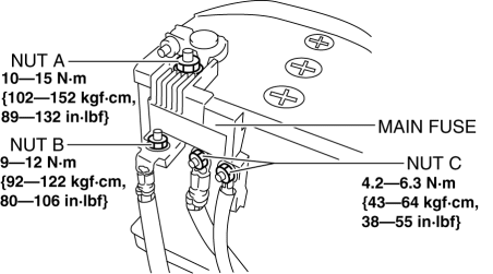
4. Remove the main fuse.
5. Install in the reverse order of removal.
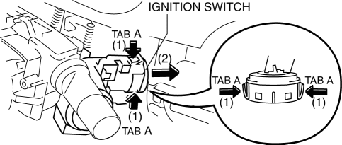
IGNITION SWITCH REMOVAL/INSTALLATION
1. Disconnect the negative battery cable.
2. Remove the column cover. (See COLUMN COVER REMOVAL/INSTALLATION).
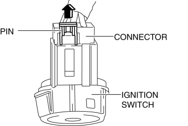
3. Press tabs A in the direction of the arrow (1) shown in the figure and pull the ignition switch in the direction of the arrow (2).
4. Pull the pin in the direction of the arrow shown in the figure and release the lock.
5. Pull the connector in the direction of the arrow (4) shown in the figure and remove it while pressing tab B in the direction of the arrow (3).
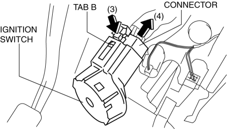
6. Remove the ignition switch.
7. Install in the reverse order of removal.
IGNITION SWITCH INSPECTION
1. Disconnect the negative battery cable.
2. Remove the column cover. (See COLUMN COVER REMOVAL/INSTALLATION).
3. Remove the ignition switch. (See IGNITION SWITCH REMOVAL/INSTALLATION).
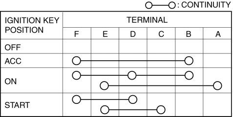
4. Verify that the continuity between the ignition switch terminals is as indicated in the table.
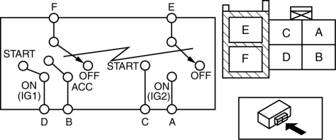
- If not as indicated in the table, replace the ignition switch.
KEY REMINDER SWITCH REMOVAL/INSTALLATION
1. Disconnect the negative battery cable.
2. Remove the column cover. (See COLUMN COVER REMOVAL/INSTALLATION).
3. Remove the coil antenna. (See COIL ANTENNA REMOVAL/INSTALLATION).
4. Insert the key into the key cylinder and turn the ignition switch to the ACC position.
5. Disconnect the key reminder switch connector.
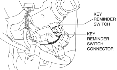
6. Detach the key reminder switch tab.
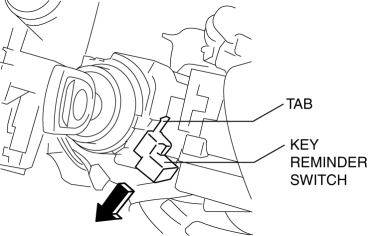
7. Install the key reminder switch in the direction of the arrow.
8. Install in the reverse order of removal.
KEY REMINDER SWITCH INSPECTION
1. Disconnect the negative battery cable.
2. Remove the column cover. (See COLUMN COVER REMOVAL/INSTALLATION).
3. Disconnect the key reminder switch connector.

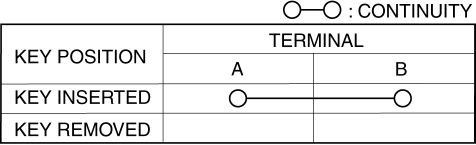
4. Verify that the continuity between the key reminder switch terminals is as indicated in the table.
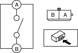
- If not as indicated in the table, replace the key reminder switch.
RELAY LOCATION
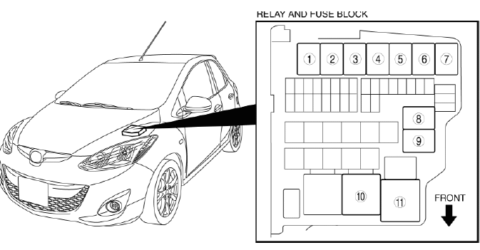
- Front fog light relay
- Starter relay
- A/C relay
- Horn relay
- Cooling fan relay No.1
- Headlight relay (HI)
- Fuel pump relay
- Cooling fan relay No.2
- Headlight relay (LO)
- Blower relay
- Main relay
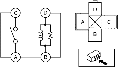
RELAY INSPECTION
Relay Type
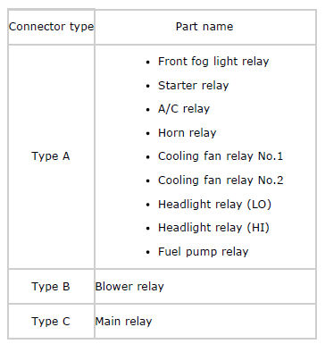
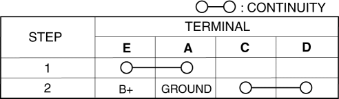
Type A
1. Verify that the continuity is as indicated in the table.
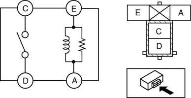
- If not as indicated in the table, replace the relay.
Type B
1. Verify that the continuity is as indicated in the table.
- If not as indicated in the table, replace the relay.

Type C
1. Verify that the continuity is as indicated in the table.
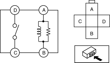
- If not as indicated in the table, replace the relay.


