Mazda 2: Instrumentation/Driver Info.
INSTRUMENTATION/DRIVER INFO. LOCATION INDEX
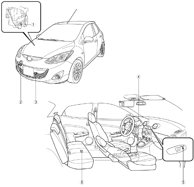
- Oil pressure switch
- Horn
- Ambient temperature sensor
- Instrument cluster
- Passenger seat belt reminder
- Fuel gauge sender unit
INSTRUMENT CLUSTER REMOVAL/INSTALLATION
CAUTION:
- When replacing the instrument cluster, always perform the configuration procedure before removing the instrument cluster. Replacing the instrument cluster without performing the configuration procedure will result in system malfunction.
1. When replacing the instrument cluster, always perform the configuration procedure. (See INSTRUMENT CLUSTER CONFIGURATION).
2. Disconnect the negative battery cable.
3. Remove the meter hood. (See METER HOOD REMOVAL/INSTALLATION).
4. Remove in the order indicated in the table.
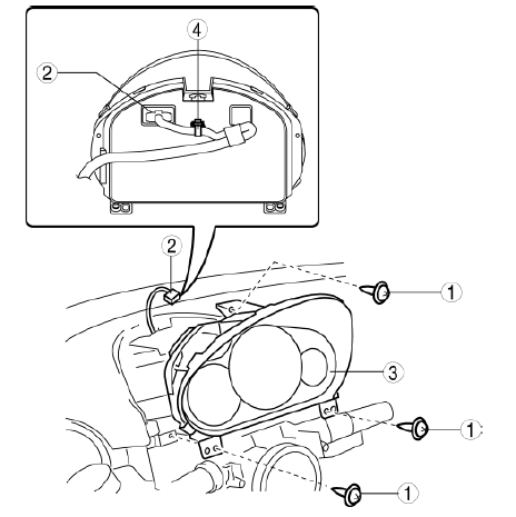
- Screw
- Connector
- Instrument cluster
- Wiring harness clip
5. Install in the reverse order of removal.
6. Program the immobilizer system-related parts when replacing the instrument cluster. (See IMMOBILIZER SYSTEM-RELATED PARTS PROGRAMMING [KEYLESS ENTRY SYSTEM] ).
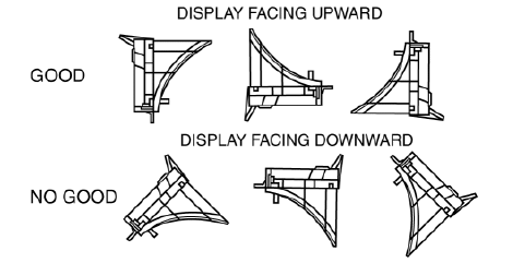
CAUTION:
- Place the removed instrument cluster with the display surface facing upward. Otherwise grease could leak from the meter unit.
INSTRUMENT CLUSTER CONFIGURATION
1. Connect the M-MDS (IDS) to DLC-2.
2. After the vehicle is identified, select the following items from the initial screen of the M-MDS.
- Select the "Module Programming"
- Select the "Programmable Module Installation".
- Select the "IC"
3. Perform the configuration according to the directions on the screen.
4. Retrieve DTCs by the M-MDS, then verify that there is no DTC present.
- If a DTC (s) is detected, perform the applicable DTC inspection. (See DTC TABLE [INSTRUMENT CLUSTER] ).
INSTRUMENT CLUSTER DISASSEMBLY/ASSEMBLY
CAUTION:
- Do not drop the instrument cluster or damage the printed board. This will lead to a system malfunction.
1. Disconnect the negative battery cable.
2. Remove the meter hood. (See METER HOOD REMOVAL/INSTALLATION).
3. Remove the instrument cluster. (See INSTRUMENT CLUSTER REMOVAL/INSTALLATION).
4. Disassemble in the order indicated in the figure.
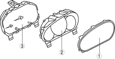
- Lens
- Cover
- Instrument cluster unit
5. Assemble in the reverse order of disassembly.
INSTRUMENT CLUSTER INSPECTION
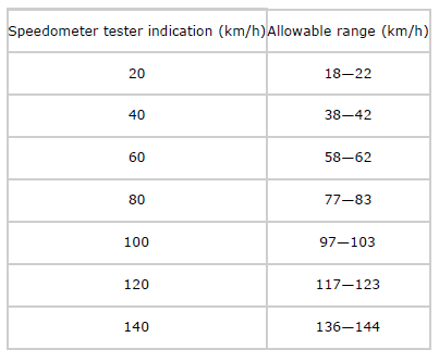
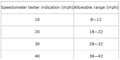
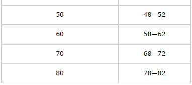
Speedometer
1. Adjust the tire pressure to the specification.
2. Using a speedometer tester, verify that the tester reading is as indicated in the table.
- If the speedometer does not operate or the indication is not within the
allowable range, inspect the PCM and related wiring harnesses.
- If the PCM and related wiring harnesses do not have any malfunction, replace the instrument cluster.
Tachometer
CAUTION:
- If the engine speed exceeds the allowable range, the engine could be
damaged.
Therefore, when inspecting the tachometer, do not allow the engine speed to exceed the allowable range indication on the tachometer.
1. Connect the M-MDS (IDS) to the DLC-2.
2. After the vehicle is identified, select the following items from the initialization screen of the IDS.
- Select "Data logger"
- Select "Module"
- Select "IC"
3. Select "TACHOMTR" from PID/DATA monitor table.
4. Verify the monitored value according to the directions on the screen.
NOTE:
- The PID data screen function is used for monitoring the calculated value of input/output signals in the module. Therefore, if the monitored value of the output parts is not within the specification, it is necessary to inspect the monitored value of input parts corresponding to the applicable output part control. In addition, because the system does not display an output part malfunction as an abnormality in the monitored value, it is necessary to inspect the output parts individually.
Fuel gauge
1. Connect the M-MDS (IDS) to the DLC-2.
2. After the vehicle is identified, select the following items from the initialization screen of the IDS.
- Select "Data logger"
- Select "Module"
- Select "IC"
3. Verify that all the segments are displayed using "LCD_SEG".

- If any of the segments are not displayed, replace the instrument
cluster.
(See INSTRUMENT CLUSTER REMOVAL/INSTALLATION).
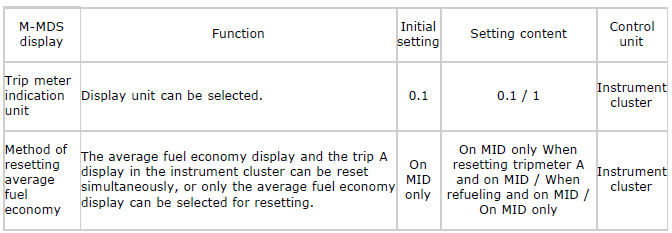
INSTRUMENT CLUSTER CUSTOMIZED FUNCTION SETTING PROCEDURE
1. Connect the M-MDS (IDS) to the DLC-2.
2. After vehicle identification, the following can be selected from the M-MDS initialization screen.
- Select the "Module Programming".
3. Then, select items from the screen menu in the following order.
- Select "Programmable Parameters".
- Select "IC".
4. Select the item name, and then select option.
FUEL GAUGE SENDER UNIT REMOVAL/INSTALLATION
- When removing/installing the fuel gauge sender unit, refer to the procedure, "FUEL PUMP UNIT DISASSEMBLY/ASSEMBLY". (See FUEL PUMP UNIT DISASSEMBLY/ASSEMBLY] ).
1. Disconnect the negative battery cable.
2. Remove the fuel pump unit. (See FUEL PUMP UNIT REMOVAL/INSTALLATION] ).
3. Move the float to the topmost and bottommost positions, and verify that the resistance between terminals C and D of the fuel gauge sender unit and the position of the float are as shown in the figure.
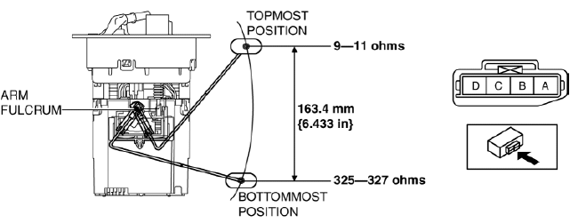
- If they are not as shown in the figure, replace the fuel gauge sender unit.
OIL PRESSURE SWITCH INSPECTION
1. Turn the ignition switch to the ON position and verify that the oil pressure warning light illuminates.
2. Start the engine and verify that the oil pressure warning light turns off.
- If the oil pressure warning light does not illuminate or remains
illuminated, inspect the BCM and the related wiring harnesses. (See DTC
INSPECTION [BCM] ).
- If the related wiring harnesses are normal, inspect the oil
pressure. (See OIL PRESSURE INSPECTION] ).
- If the oil pressure is normal, replace the oil pressure switch.
- If the related wiring harnesses are normal, inspect the oil
pressure. (See OIL PRESSURE INSPECTION] ).
AMBIENT TEMPERATURE SENSOR REMOVAL/INSTALLATION
1. Disconnect the negative battery cable.
2. Remove the front bumper. (See FRONT BUMPER REMOVAL/INSTALLATION).
3. Remove in the order indicated in the table.
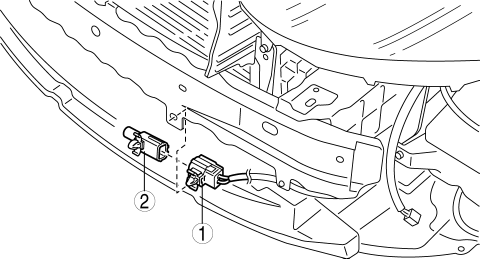
- Connector
- Ambient temperature sensor
4. Install in the reverse order of removal.
AMBIENT TEMPERATURE SENSOR INSPECTION
NOTE:
- The ambient temperature sensor does not directly respond to sudden changes in surrounding temperature (such as when traveling through a highway tunnel, or direct and intermittent sunlight). Therefore, if the resistance is measured immediately after the ambient temperature sensor is removed, the reading could be different from the actual value.
1. Leave the ambient temperature sensor where the inspection is to be performed for 30 min or more after removing it.
2. Measure the resistance between terminals of the ambient temperature sensor.
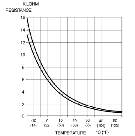
- If the resistance is not as shown in the graph, replace the ambient temperature sensor.
HORN REMOVAL/INSTALLATION
1. Disconnect the negative battery cable.
2. Remove the front bumper. (See FRONT BUMPER REMOVAL/INSTALLATION).
3. Remove the clip.
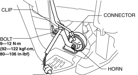
4. Disconnect the connector.
5. Remove the bolt.
6. Remove the horn.
7. Install in the reverse order of removal.
PASSENGER SEAT BELT REMINDER REMOVAL/INSTALLATION
NOTE:
- The passenger seat belt reminder is built into the hazard warning switch panel.
1. Remove the passenger seat belt reminder. (See CENTER PANEL UNIT DISASSEMBLY/ASSEMBLY).
PASSENGER SEAT BELT REMINDER INSPECTION
1. Remove the passenger seat belt reminder. (See CENTER PANEL UNIT DISASSEMBLY/ASSEMBLY).
2. Apply battery positive voltage to passenger seat belt reminder terminal A, and connect terminal B to ground.
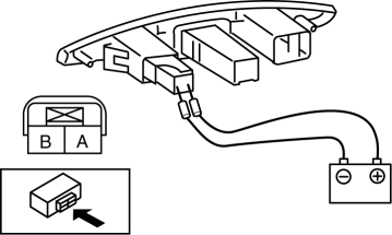
3. Verify that the LED illuminates.
- If the LED does not illuminate, replace the passenger seat belt reminder.

