Mazda 2: Starting System
STARTING SYSTEM LOCATION INDEX
- Starter interlock switch (MTX)
- (See STARTER INTERLOCK SWITCH INSPECTION)
- Starter
- (See STARTER REMOVAL/INSTALLATION)
- (See STARTER INSPECTION)
- (See STARTER DISASSEMBLY/ASSEMBLY)
STARTER REMOVAL/INSTALLATION
WARNING:
- Remove and install all parts when the engine is cold, otherwise they can cause severe burns or serious injury.
- When the battery cables are connected, touching the vehicle body with starter terminal B will generate sparks. This can cause personal injury, fire, and damage to the electrical components. Always disconnect the negative battery cable before performing the following operation.
1. Disconnect the negative battery cable.
2. Perform the following procedure. (ATX)
CAUTION:
- Removing the fresh-air duct from the air cleaner case may damage the fresh-air duct. Remove the fresh-air duct and the air cleaner case as a single unit except when the fresh-air duct is to be replaced with a new one.
- Remove the fresh-air duct and air cleaner as a single unit. (See INTAKE-AIR SYSTEM REMOVAL/INSTALLATION).
3. Remove in the order indicated in the table.
4. Install in the reverse order of removal.
- Terminal B cable
- Terminal S connector
- Starter
Starter Removal Note
ATX
1. Remove the starter upper bolt from above the engine compartment.
2. Remove the starter lower bolt and starter from below the engine compartment.
MTX
1. Remove the starter bolts (upper, lower) and starter from below the engine compartment.
Starter Installation Note (ATX)
CAUTION:
- Do not overlap the starter with the end plate (area A shown in figure) when installing. If the starter is not correctly installed, the nut installed to the drive plate may contact the end plate causing abnormal noise.
STARTER INSPECTION
On-vehicle Inspection
1. Verify that the battery is fully charged.
2. The starter is normal if it rotates smoothly and without any noise when the engine is cranked.
- If the starter does not operate, inspect the following:
- Remove the starter, and inspect the starter unit.
- Inspect the related wiring harnesses, the ignition switch, and the transaxle range switch (ATX) or starter interlock switch (MTX).
No-load Test
1. Verify that the battery is fully charged.
2. Connect the starter, battery, and a tester as shown in the figure.
3. Operate the starter and verify that it rotates smoothly.
- If the starter does not rotate smoothly, inspect the starter unit.
4. Measure the voltage and current while the starter is operating.
- If not within specification, replace the starter.
Starter no-load test voltage
- 11 V
Starter no-load test current
- MTX: 95 A or less
- ATX: 90 A or less
Magnetic Switch Operation Inspection
Pull-out test
NOTE:
- Depending on the battery charge condition, the starter motor pinion may rotate while in an extended state. This is due to current flowing to the starter motor through the pull-in coil to turn the starter motor, and does not indicate an abnormality.
1. Verify that the starter motor pinion is extended while battery positive voltage is connected to terminal S and the starter body is grounded.

- If the starter motor pinion is not extended, repair or replace the starter.
Return test
1. Disconnect the motor wire from terminal M.
2. Connect battery positive voltage to terminal M and ground the starter body.
3. Pull out the drive pinion with a screwdriver. Verify that it returns to its original position when released.
- If it does not return, repair or replace the starter.
Pinion Gap Inspection
1. Pull out the drive pinion with the battery positive voltage connected to terminal S and the starter body grounded.
CAUTION:
- Applying power for more than 10 s can damage the starter. Do not apply power for more than 10 s.
2. Measure the pinion gap while the drive pinion is extended.
- If not as specified, adjust with an adjustment washer (between drive housing front cover and magnetic switch).
Starter pinion gap
- 0.5-2.0 mm {0.02-0.07 in}
Starter Inner Parts Inspection
Armature
1. Verify that there is no continuity between the commutator and the core at each segment using a tester.
- If there is continuity, replace the armature.
2. Verify that there is no continuity between the commutator and the shaft using a tester.
- If there is continuity, replace the armature.
3. Place the armature on V-blocks, and measure the runout using a dial indicator.
- If it exceeds the maximum specification, replace the armature.
Starter armature runout
- 0.1 mm {0.004 in} max.
4. Measure the commutator diameter.
- If not within the minimum specification, replace the armature.
Starter commutator diameter
- Standard: 29.4 mm {1.16 in}
- Minimum: 28.8 mm {1.13 in}
5. Measure the segment groove depth of the commutator.
- If not within the minimum specification, undercut the grooves to the standard depth.
Segment groove depth of starter commutator
- Standard: 0.5 mm {0.02 in}
- Minimum: 0.2 mm {0.008 in}
Magnetic switch
1. Inspect for continuity between terminals S and M using a tester.
- If there is no continuity, replace the magnetic switch.
2. Inspect for continuity between terminal S and the body using a tester.
- If there is no continuity, replace the magnetic switch.
3. Verify that there is no continuity between terminals M and B using a tester.
- If there is continuity, replace the magnetic switch.
Brush and brush holder
1. Verify that there is no continuity between each insulated brush and plate using a tester.
- If there is continuity, replace the brush holder.
2. Measure the brush length.
- If any brush is worn almost to or beyond the minimum specification, replace all of the brushes.
Starter brush length
- Standard: 12.3 mm {0.484 in}
- Minimum: 5.5 mm {0.22 in}
3. Measure the brush spring force using a spring balance.
- If not within the minimum specification, replace the brush and brush holder component.
Starter brush spring force
- Standard: 15.0-20.4 N {1.53-2.08 kgf, 3.38-4.58 lbf}
- Minimum: 2.75 N {0.280 kgf, 0.618 lbf}
STARTER DISASSEMBLY/ASSEMBLY
1. Disassemble in the order indicated in the table.
2. Assemble in the reverse order of disassembly.
- Magnetic switch
- Adjustment washer
- Rear housing
- Brush and brush holder
- Armature
- Yoke
- Planetary gear
- Front cover
- Lever
- Drive pinion
- Internal gear
- Gear shaft
STARTER INTERLOCK SWITCH INSPECTION
CAUTION:
- Do not reuse the starter interlock switch if it is removed from the
vehicle even once.
Replace with a new starter interlock switch when installing.
1. Disconnect the negative battery cable.
2. Disconnect the starter interlock switch connector.
3. Verify that the continuity is as indicated in the table using a tester.
- If the continuity is not as indicated in the table, replace the starter
interlock
switch.
(See CLUTCH PEDAL REMOVAL/INSTALLATION).
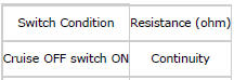
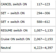
CRUISE CONTROL SWITCH INSPECTION
1. Switch the ignition to off.
2. Disconnect the negative battery cable and wait for 1 min or more.
3. Remove the driver-side air bag module. (See DRIVER-SIDE AIR BAG MODULE REMOVAL/INSTALLATION).
4. Disconnect the clock spring connector (part wiring harness-side).
5. Inspect for resistance and continuity between clock spring terminals B and D (part wiring harness-side) using a tester.
- If not as specified, replace the audio control switch. (See AUDIO CONTROL SWITCH REMOVAL/INSTALLATION).
6. Apply battery positive voltage to clock spring terminal G (part wiring harness-side) and terminal E (part wiring harness-side) to ground.
7. Verify that the LED illuminates.
- If the LED does not illuminate, replace the audio control switch. (See AUDIO CONTROL SWITCH REMOVAL/INSTALLATION).

