Mazda 2: PCM
PCM REMOVAL/INSTALLATION
CAUTION:
- The PCM is built into the air cleaner cover. Applying excessive pressure to the cover could damage the PCM. Be careful not to put your hands on the PCM during the removal/installation.
- Removing the PCM from the air cleaner cover could damage the sealing or
the circuitry.
Do not remove the PCM from the air cleaner cover.
1. Remove the air cleaner cover. (See INTAKE-AIR SYSTEM REMOVAL/INSTALLATION).
2. Install in the reverse order of removal.
3. When replacing the PCM on the vehicles, perform the following:
- PCM configuration (See PCM CONFIGURATION).
- PCM parameter reset (See IMMOBILIZER SYSTEM-RELATED PARTS PROGRAMMING [KEYLESS ENTRY SYSTEM] ).
PCM INSPECTION
Without Using the M-MDS
CAUTION:
- The PCM terminal voltages vary with change in measuring conditions and vehicle conditions. Always carry out a total inspection of the input systems, output systems, and PCM to determine the cause of trouble. Otherwise, a wrong diagnosis will be made.
1. Measure the voltage at each terminal.
- If any incorrect voltage is detected, inspect the related system(s), wiring harnesses and connector(s) referring to the Action column in the terminal voltage table.
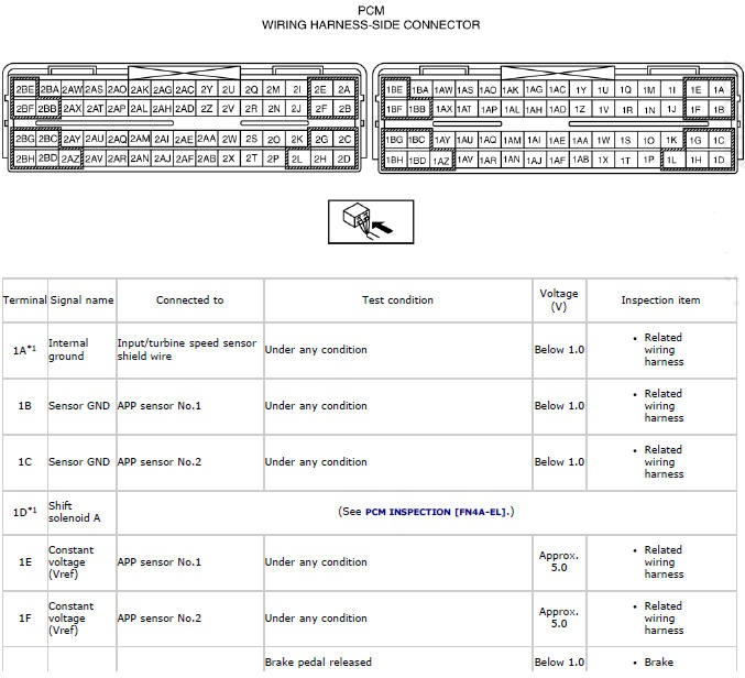
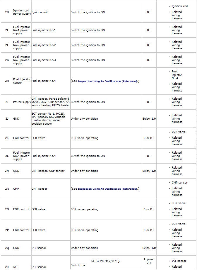
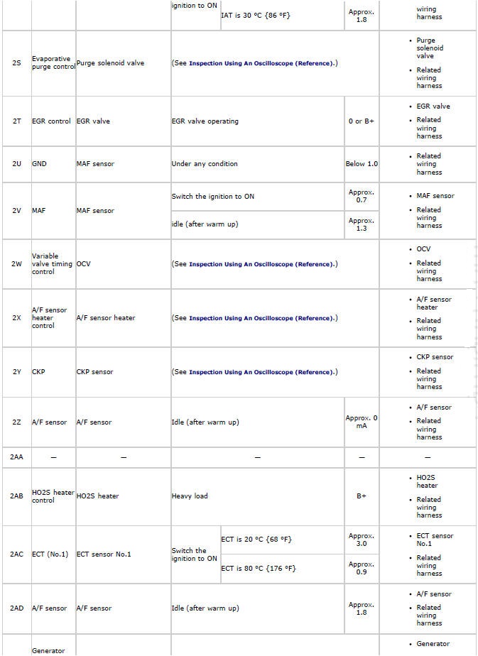
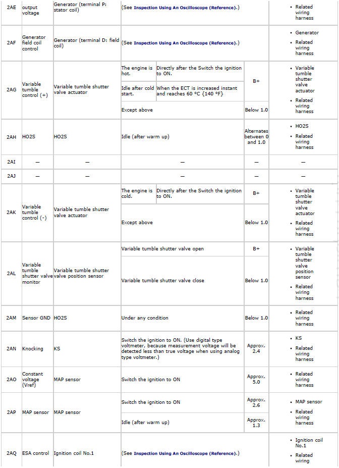
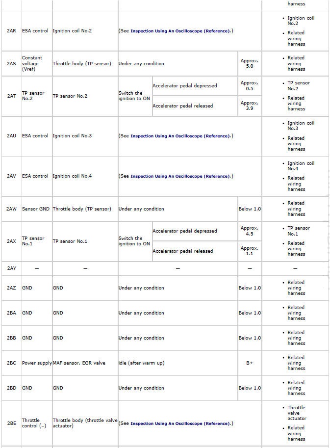
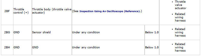
PCM Terminal Voltage Table (Reference)
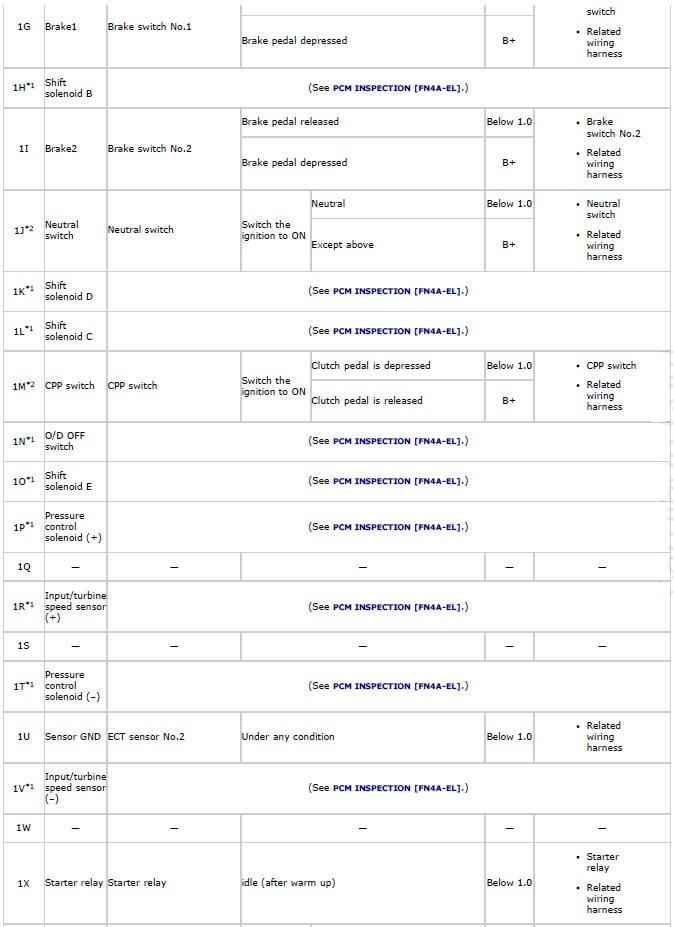
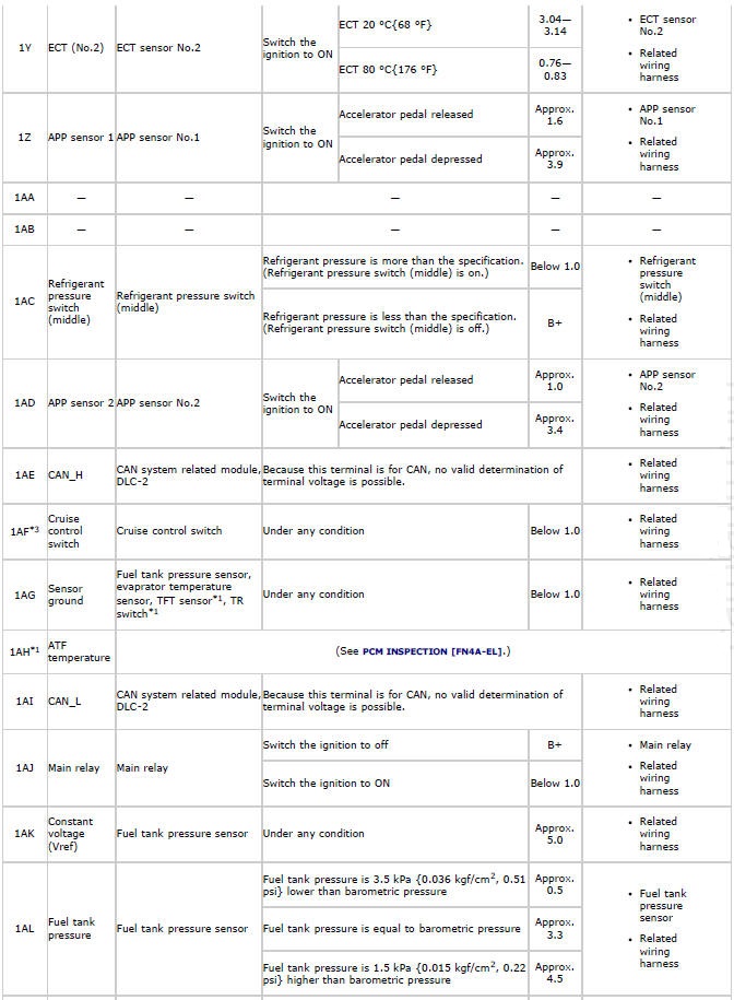
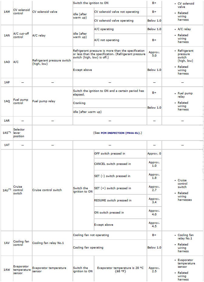
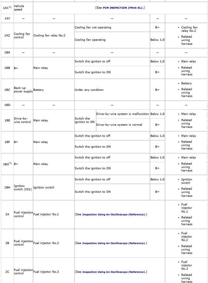
*1 ATX
*2 MTX
*3 With cruise control system
Inspection Using An Oscilloscope (Reference)
Fuel injection control signal
PCM terminals
- Fuel injector No.1: 2A (+)-Negative battery terminal (-)
- Fuel injector No.2: 2B (+)-Negative battery terminal (-)
- Fuel injector No.3: 2C (+)-Negative battery terminal (-)
- Fuel injector No.4: 2H (+)-Negative battery terminal (-)
Oscilloscope setting
- 5 V/DIV (Y), 10 ms/DIV (X), DC range
Vehicle condition
- idle (after warm up)
CMP signal
PCM terminals
- 2N (+)-Negative battery terminal (-)
Oscilloscope setting
- 1 V/DIV (Y), 20 ms/DIV (X), DC range
Vehicle condition
- idle (after warm up)
Evaporative purge control signal
PCM terminals
- 2S (+)-Negative battery terminal (-)
Oscilloscope setting
- 10 V/DIV (Y), 20 ms/DIV (X), DC range
Vehicle condition
- idle (after warm up)
Variable valve timing control signal
PCM terminals
- 2W (+)-Negative battery terminal (-)
Oscilloscope setting
- 10 V/DIV (Y), 10 ms/DIV (X), DC range
Vehicle condition
- idle (after warm up)
A/F sensor heater control signal
PCM terminals
- 2X (+)-Negative battery terminal (-)
Oscilloscope setting
- 5 V/DIV (Y), 50 ms/DIV (X), DC range
Vehicle condition
- idle (after warm up)
CKP signal
PCM terminals
- 2Y(+)-Negative battery terminal (-)
Oscilloscope setting
- 5 V/DIV (Y), 5 ms/DIV (X), DC range
Vehicle condition
- idle (after warm up)
Generator output voltage signal
PCM terminals
- 2AE (+)-Negative battery terminal (-)
Oscilloscope setting
- 2 V/DIV (Y), 1 ms/DIV (X), DC range
Vehicle condition
- idle (after warm up)
Generator field coil control signal
PCM terminals
- 2AF (+)-Negative battery terminal (-)
Oscilloscope setting
- 0.5 V/DIV (Y), 1 ms/DIV (X), DC range
Vehicle condition
- idle (after warm up)
ESA control signal
PCM terminals (except for California emission regulation applicable model)
- Ignition coil No.1: 2AQ (+)-Negative battery terminal (-)
- Ignition coil No.2: 2AR (+)-Negative battery terminal (-)
- Ignition coil No.3: 2AU (+)-Negative battery terminal (-)
- Ignition coil No.4: 2AV (+)-Negative battery terminal (-)
Oscilloscope setting
- 0.5 V/DIV (Y), 40 ms/DIV (X), DC range
Vehicle condition
- idle (after warm up)
Throttle control (-) signal
PCM terminals
- 2BE (+)-Negative battery terminal (-)
Oscilloscope setting
- 10 V/DIV (Y), 1 ms/DIV (X), DC range
Vehicle condition
- idle (after warm up)
Throttle control (+) signal
PCM terminals
- 2BF (+)-Negative battery terminal (-)
Oscilloscope setting
- 5 V/DIV (Y), 0.4 ms/DIV (X), DC range
Vehicle condition
- Switch the ignition to ON.
Using The M-MDS
NOTE:
- PIDs for the following parts are not available on this model. Go to the
appropriate part inspection page.
- CMP sensor (See CAMSHAFT POSITION (CMP) SENSOR INSPECTION).
- Main relay (See RELAY INSPECTION).
1. Connect the M-MDS to the DLC-2.
2. Turn the ignition switch to the ON position.
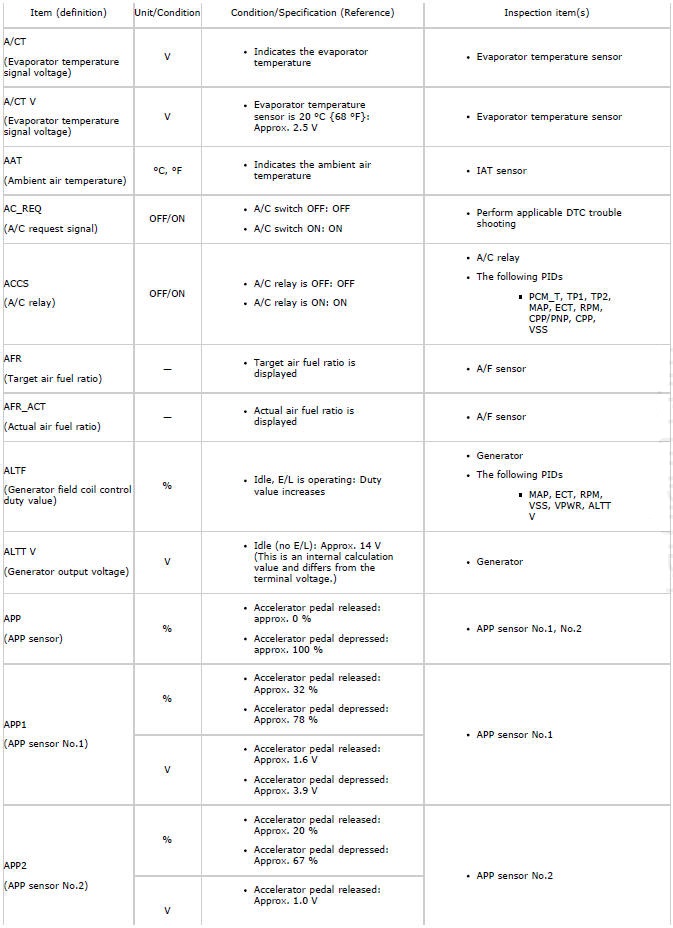
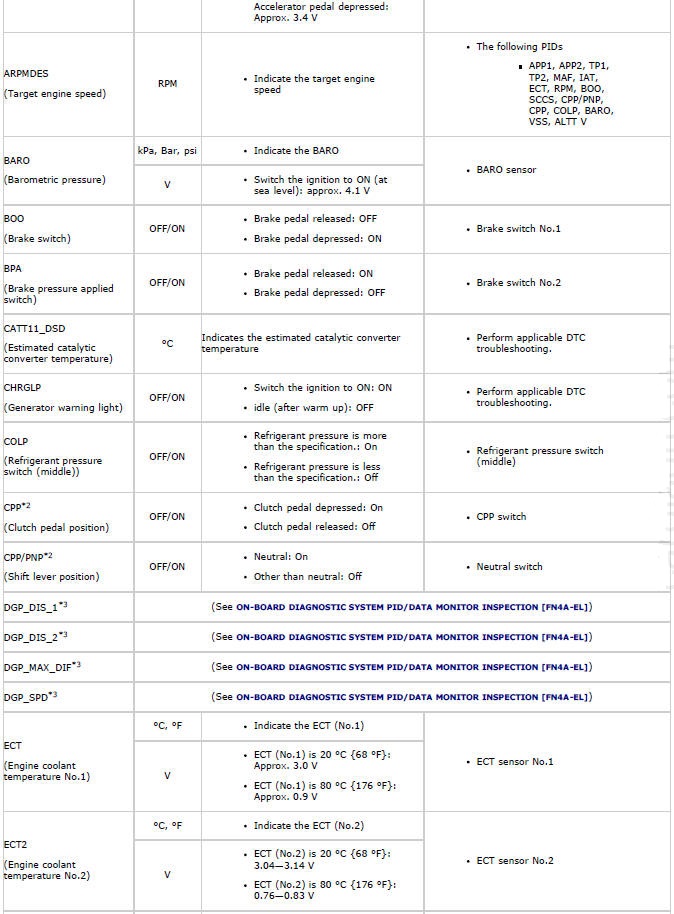
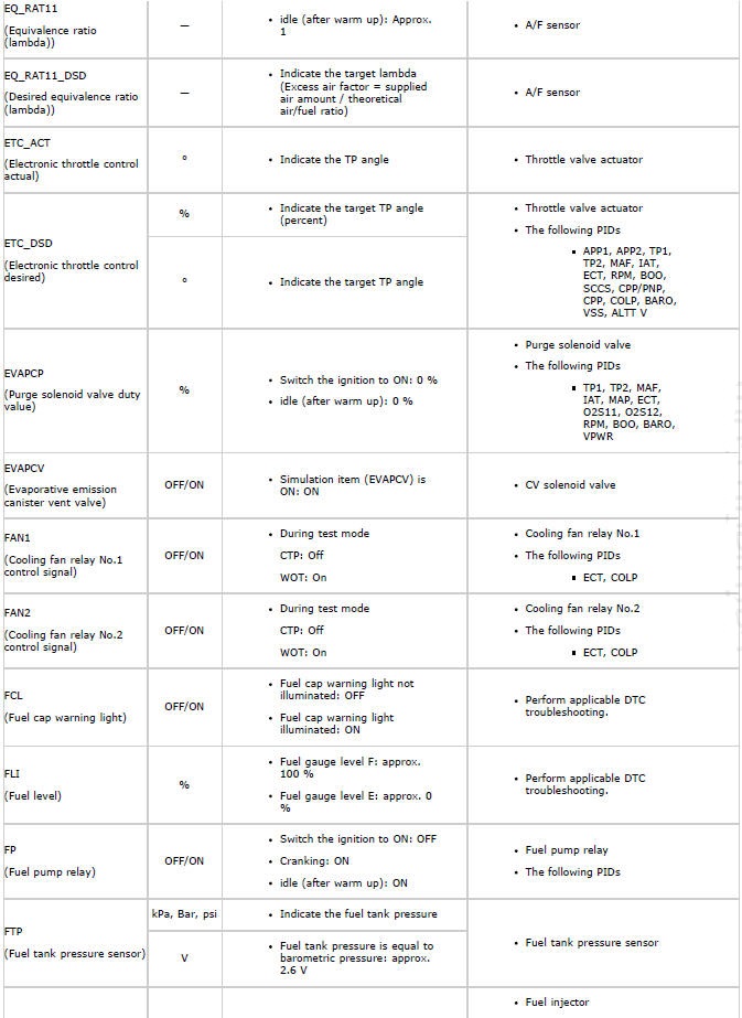
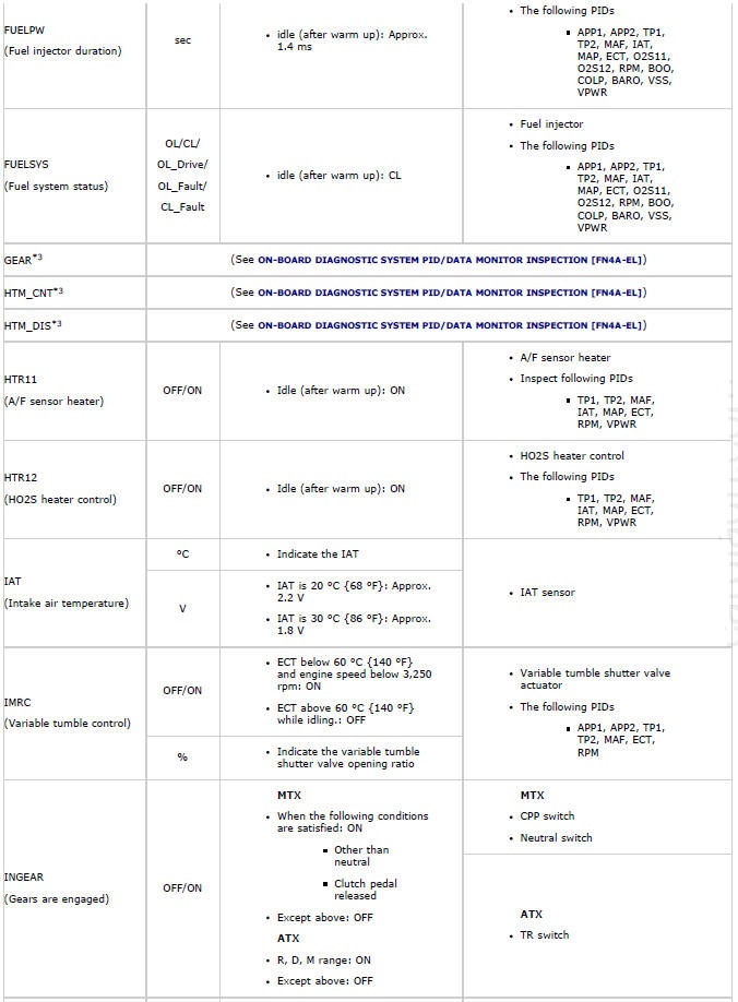
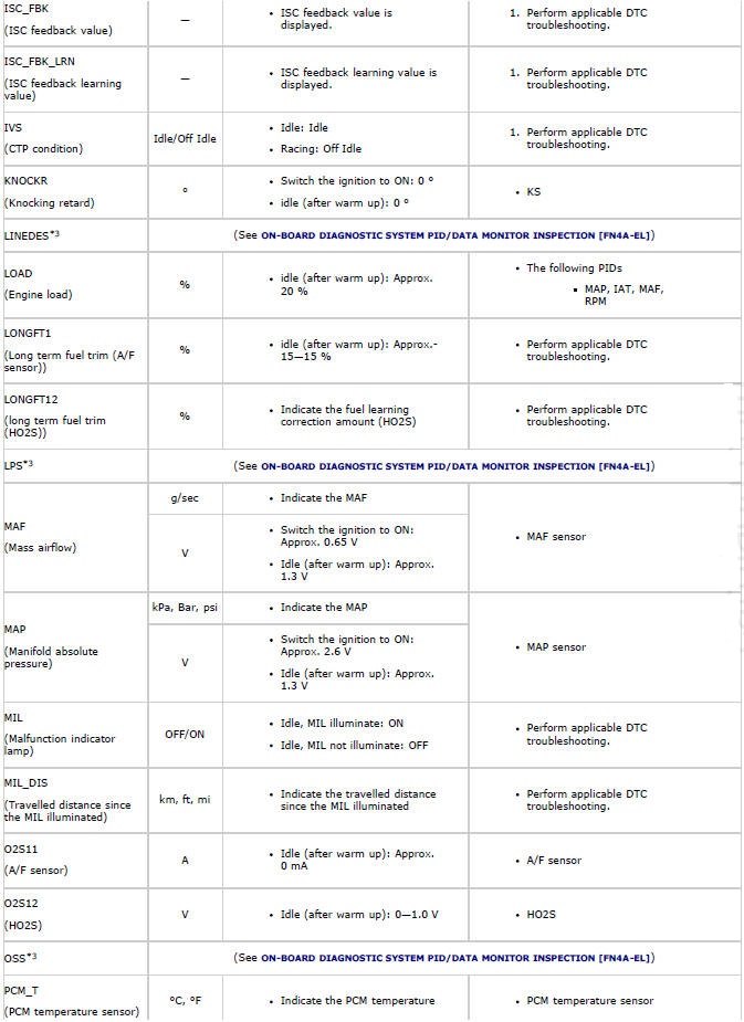
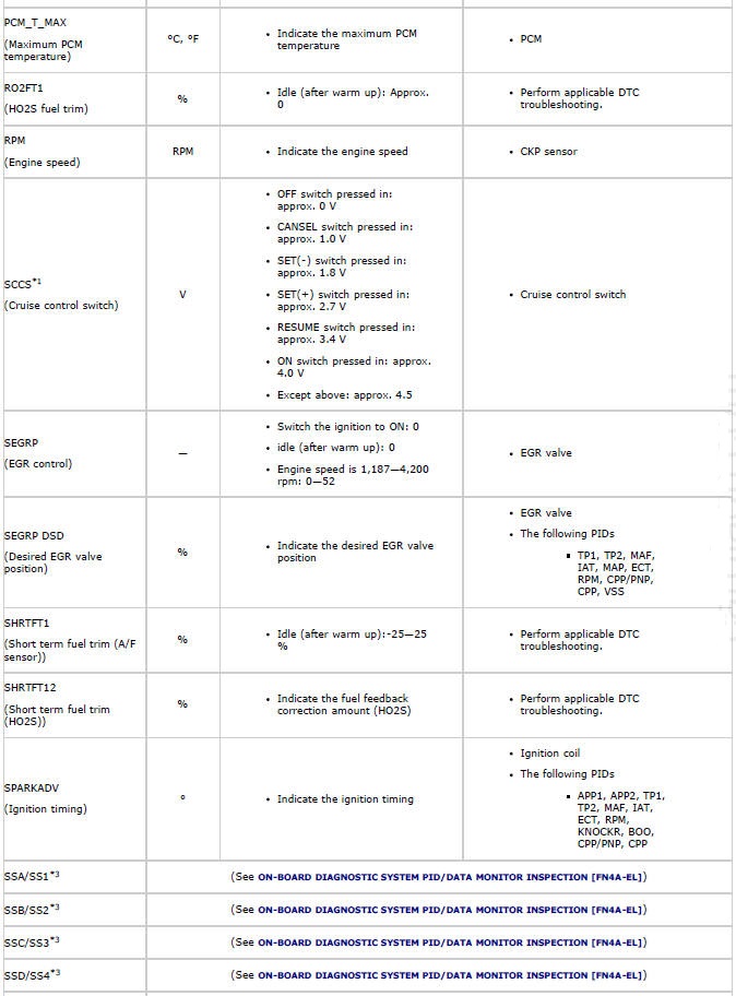
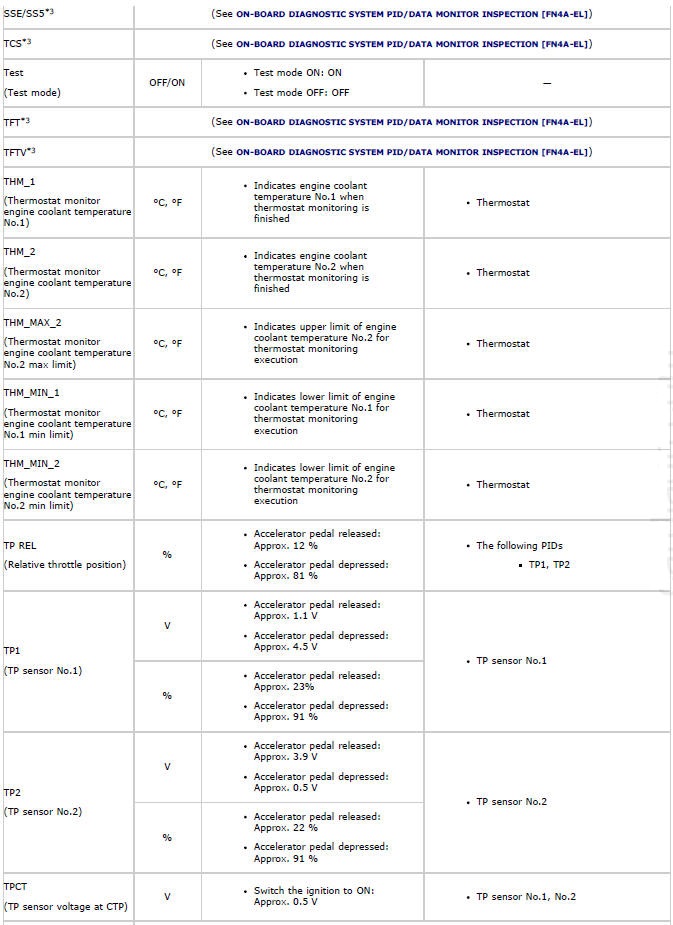
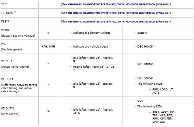
3. Measure the PID value.
- If PID value is not within the specification, follow the instructions in Action column.
NOTE:
- The PID/DATA MONITOR function monitors the calculated value of the input/output signals in the PCM. Therefore, an output device malfunction is not directly indicated as a malfunction of the monitored value for the output device. If a monitored value of an output device is out of specification, inspect the monitored value of the input device related to the output control.
- The simulation items that are used in the ENGINE CONTROL SYSTEM
OPERATION INSPECTION are as follows.
- ACCS, ALTF, ARPMDES, EVAPCP, EVAPCV, FAN1, FAN2, FP, IMRC, INJ_1, INJ_2, INJ_3, INJ_4, SEGRP, Test, VT Duty1 wt
*1 With cruise control system
*2 MTX
*3 ATX
PCM CONFIGURATION
1. Connect the M-MDS (IDS) to the DLC-2.
2. After the vehicle is identified, select the following items from the initial screen of the M-MDS.
- When using the IDS (laptop PC)
- Select "Module Programming".
- Select "Programmable Module Installation".
- Select "PCM".
3. Perform the configuration according to the directions on the screen.
4. Retrieve DTCs by the M-MDS, then verify that there is no DTC present.
- If a DTC (s) is detected, perform the applicable DTC inspection. (See DTC TABLE).

