Mazda 2: Brake Hose (Front)
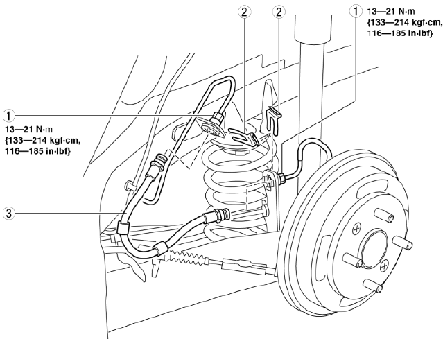
BRAKE HOSE (FRONT) REMOVAL/INSTALLATION
1. Remove in the order indicated in the table.
2. Install in the reverse order of removal.
3. Add brake fluid, bleed the brakes, and inspect for leakage after the installation has been completed. (See BRAKE FLUID AIR BLEEDING).
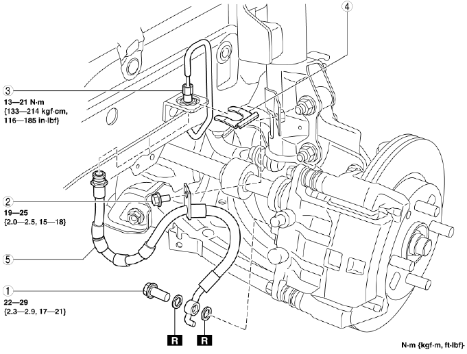
- Bolt
- Bolt
- Brake pipe
- Clip
- Brake hose
REAR BRAKE (DRUM) INSPECTION
Brake Lining Thickness Inspection
1. Remove the brake drum and measure the thickness of the brake lining.
- If it is less than the minimum specification, replace the brake shoe.
Minimum brake lining thickness
- 1.0 mm {0.039 in}
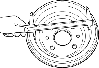
Brake Drum Inspection
1. Remove the drum component.
2. Measure the inner diameter of the brake drum.
- If there is marked partial wear of the brake drum, grind the surface to within the maximum brake drum inner diameter or replace it.
Brake drum wear maximum
- 201.5 mm {7.933 in}
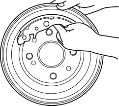
3. Apply chalk to the inside of the brake drum, rub it against the brake shoe, and then inspect for scratches and uneven or abnormal wear inside the drum.
- If there is marked partial wear of the brake drum, grind the surface to within the maximum brake drum inner diameter or replace it.
4. After inspection, wipe the chalk off.
REAR BRAKE (DRUM) REMOVAL/INSTALLATION
WARNING:
- When removing/installing the brake drum component parts, the spring could fly off and cause injury. Remove/install the spring being careful not to allow the spring to fly off. Wear protective equipment such as safety glasses if necessary.
1. Remove in the order indicated in the table.
2. Install in the reverse order of removal.
3. Add brake fluid, bleed the brakes, and inspect for leakage after the installation has been completed. (See BRAKE FLUID AIR BLEEDING).
4. After installation, adjust the parking brake and inspect the following.
- If there is any malfunction, adjust the applicable part.
- After depressing the brake pedal several times verify that there is no brake drag.
- Brake pedal-to-floor clearance inspection (See BRAKE PEDAL INSPECTION).
- Parking brake lever stroke inspection (See PARKING BRAKE LEVER INSPECTION).
CAUTION:
- The parts securing the parking brake cable may be damaged if the parking
brake lever is pulled while the brake drum is removed.
Operate the parking brake lever only when the brake drums are installed.
NOTE:
- Excessive clearance between the brake drum and brake shoe could affect the correct operation of the automatic adjuster function. Verify that the clearance is within the specification when removing the brake drum or brake shoe, and adjust if necessary by turning the adjustment screw with a flathead screwdriver.
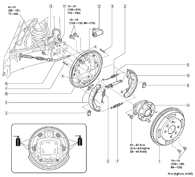
- Brake drum
- Shoe return spring (upper)
- Hold spring
- Hold pin
- Leading shoe, adjuster lever, adjust spring
- Adjuster component
- Shoe return spring (lower)
- Hold spring
- Hold pin
- Trailing shoe
- Brake pipe
- Wheel cylinder
- ABS wheel-speed sensor
- Wheel hub component
- End cable
- Backing plate
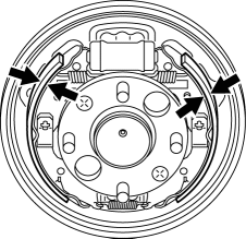
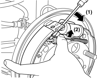
Shoe Return Spring (Upper) Removal Note
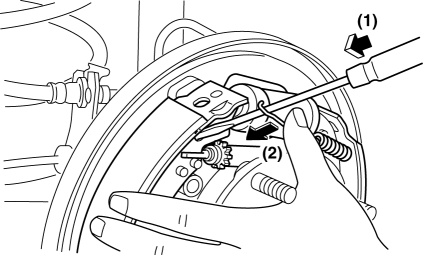
1. Remove the shoe return spring using a flathead screwdriver while supporting it with the hand, as shown in the figure, to prevent it from flying off.
Shoe Return Spring (Lower), Adjuster Component, Leading Shoe, Adjuster Lever, Adjuster spring Installation Note
1. Install the shoe return spring (lower side) to the trailing shoe.
2. Install the adjuster component to the trailing shoe.
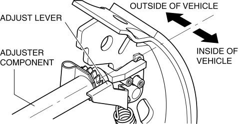
3. Install the adjuster lever and adjuster spring to the leading shoe as shown in the figure. Secure the adjuster lever so that it does not fall.
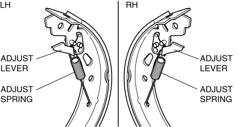
4. Install the shoe return spring (lower side) to the leading shoe.
5. Install the leading shoe, adjuster lever, and adjuster spring as a single unit as shown in the figure.
6. Verify that the adjuster component and adjuster lever are installed as shown in the figure.
NOTE:
- The parts cannot actually be seen at the same angle as shown in the figure because they are blocked by the backing plate.
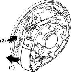
7. Reduce the outer diameter of the brake shoe and secure the adjuster lever to prevent it from falling.
NOTE:
- The adjuster lever will fall unless it is pressed by the adjuster component.
Shoe Return Spring (Upper) Installation Note
1. Install the return spring using a flathead screwdriver while supporting it with the hand, as shown in the figure, to prevent it from flying off.
Brake Drum Installation Note
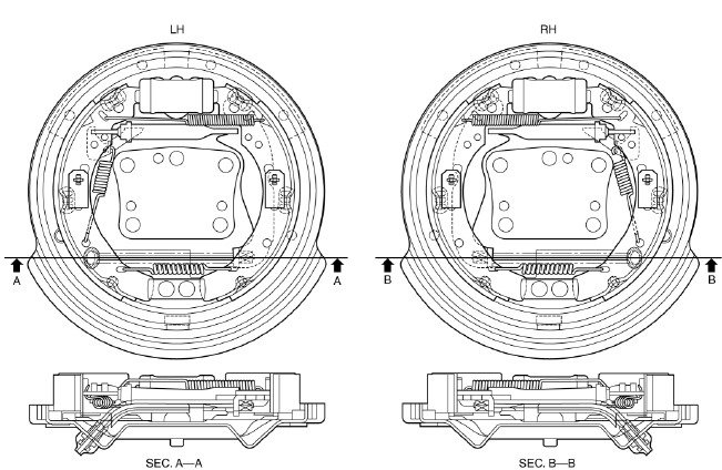
1. Verify that each component part of the brake drum is properly installed by referring to the figure.
2. Turn the adjuster on the adjuster component to adjust the brake shoe until the outer diameter (M) of the brake shoe is as specified below.
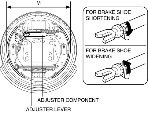
NOTE:
- Adjust the brake shoe while being careful of the adjuster lever.
Adjustment value
- 199.4-199.6 mm {7.851-7.858 in}
3. Install the brake drum.
4. Depress the brake pedal five times and operate the automatic adjuster.
5. Verify that there is no brake drag.
- If there is brake drag, readjust the brake shoe outer diameter.
WHEEL CYLINDER DISASSEMBLY/ASSEMBLY
1. Remove in the order indicated in the table.
2. Install in the reverse order of removal.
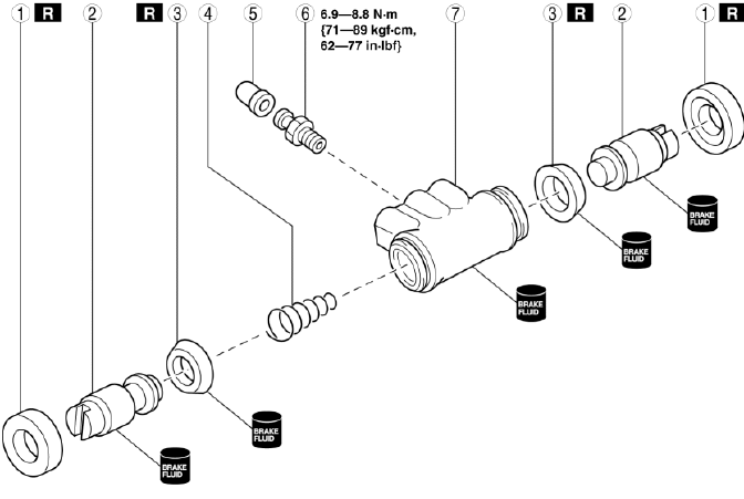
- Dust boot
- Wheel cylinder piston
- Piston cup
- Wheel cylinder spring
- Bleeder cap
- Bleeder screw
- Wheel cylinder body
BRAKE HOSE (REAR) REMOVAL/INSTALLATION
1. Remove in the order indicated in the table.
2. Install in the reverse order of removal.
3. Add brake fluid, bleed the brakes, and inspect for leakage after the installation has been completed. (See BRAKE FLUID AIR BLEEDING).
- Brake pipe
- Clip
- Brake hose

