Mazda 2: DSC
DSC LOCATION INDEX
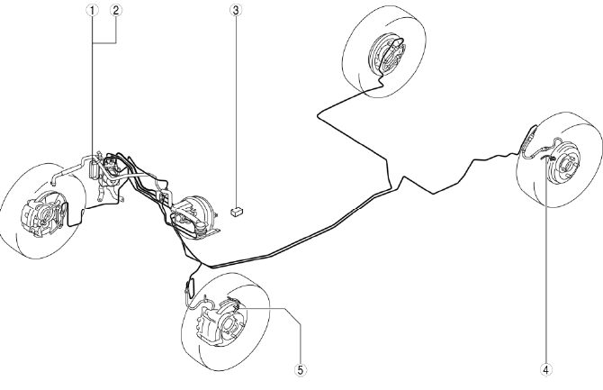
- DSC HU/CM
- (See DSC SYSTEM WIRING DIAGRAM.)
- (See DSC SYSTEM INSPECTION.)
- (See DSC HU/CM REMOVAL/INSTALLATION.)
- (See DSC HU/CM INSPECTION.)
- Brake fluid pressure sensor (Built into DSC HU/CM)
- (See BRAKE FLUID PRESSURE SENSOR INSPECTION.)
- (See DSC SENSOR INITIALIZATION PROCEDURE.)
- DSC OFF switch
- (See DSC OFF SWITCH REMOVAL/INSTALLATION.)
- (See DSC OFF SWITCH INSPECTION.)
- Rear ABS wheel-speed sensor
- (See REAR ABS WHEEL-SPEED SENSOR REMOVAL/INSTALLATION.)
- (See REAR ABS WHEEL-SPEED SENSOR INSPECTION.)
- Front ABS wheel-speed sensor
- (See FRONT ABS WHEEL-SPEED SENSOR REMOVAL/INSTALLATION.)
- (See FRONT ABS WHEEL-SPEED SENSOR REMOVAL/INSTALLATION.)
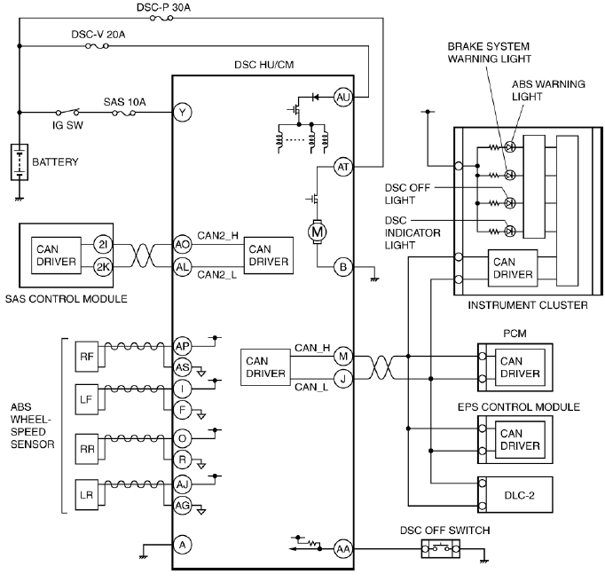
DSC SYSTEM WIRING DIAGRAM
DSC SYSTEM INSPECTION
Preparation
1. Verify that the battery is fully charged.
2. Switch the ignition to ON and verify that the ABS warning light goes out after approx. 3.0 s.
3. Switch the ignition to off.
4. Jack up the vehicle and support it evenly on safety stands.
5. Shift to the N position.
6. Verify that all four wheels rotate.
7. Rotate the inspected wheels by hand and verify there is no brake drag.
- If there is any brake drag, perform regular brake inspection.
- If there is no brake drag, perform DSC HU/CM operation inspection.
ABS Control Inspection
1. Perform "Preparation".
2. Connect the M-MDS to the DLC-2.
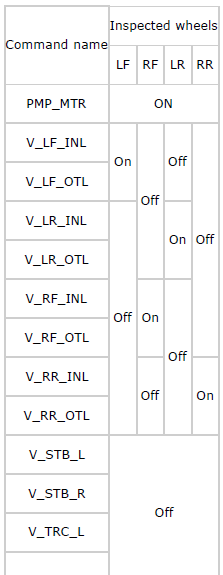
3. Set up an active command mode inspection according to the combination of commands below. (See ON-BOARD DIAGNOSIS [DYNAMIC STABILITY CONTROL (DSC)] ). Brake pressure retention
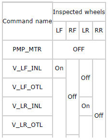
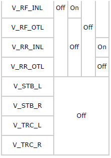
Brake pressure reduction

CAUTION:
- When operating the solenoid valve and pump motor using the active command mode, make sure to keep the operation time within 2 s to prevent damaging the DSC HU/CM.
NOTE:
- When working with two people, one should press on the brake pedal, the other should attempt to rotate the wheel being inspected.
4. Send the command while depressing on the brake pedal and attempting to rotate the wheel being inspected.
5. When brake pressure is maintained and a DSC HU/CM operation click sound is heard, confirm that the wheel does not rotate. When brake pressure is being reduced and a DSC HU/CM operation click sound is heard, confirm that the wheel rotates.
- Performing the inspection above determines the following:
- The DSC HU/CM brake lines are normal.
- The DSC HU/CM hydraulic system has no significant malfunction (including DSC HU/CM).
- The DSC HU/CM internal electrical parts (solenoid, motor and other parts) are normal.
- The DSC unit and DSC HU/CM output system wiring harnesses (solenoid valve, relay system) are normal.
- However, the following items cannot be verified.
- Intermittent malfunction of the above items
- Malfunction of DSC HU/CM input system wiring harnesses and parts
- Extremely small leakage in the DSC HU/CM internal hydraulic system
DSC Control Inspection
1. Perform "Preparation".
2. Connect the M-MDS to the DLC-2.
3. Set up an active command mode inspection according to the combination of commands below. (See ON-BOARD DIAGNOSIS [DYNAMIC STABILITY CONTROL (DSC)] ).
CAUTION:
- When operating the solenoid valve and pump motor using the active command mode, make sure to keep the operation time within 2 s to prevent damaging the DSC HU/CM.

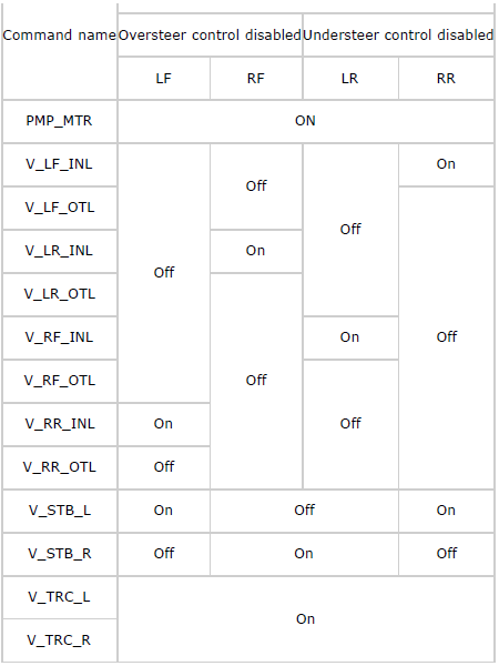
4. Send the command while rotating the wheel being inspected by hand in a forward direction.
5. Confirm that the wheel does not rotate easily while a DSC HU/CM operation click sound is heard.
- Performing the inspection above determines the following:
- The DSC HU/CM brake lines are normal.
- The DSC HU/CM hydraulic system has no significant malfunction (including DSC HU/CM).
- The DSC HU/CM internal electrical parts (solenoid, motor and other parts) are normal.
- The DSC unit and DSC HU/CM output system wiring harnesses (solenoid valve, relay system) are normal.
- However, the following items cannot be verified.
- Intermittent malfunction of the above items
- Malfunction of DSC HU/CM input system wiring harnesses and parts
- Extremely small leakage in the DSC HU/CM internal hydraulic system
DSC HU/CM REMOVAL/INSTALLATION
CAUTION:
- Always use the adapter that comes with a new DSC HU or DSC CM when separating the DSC HU or DSC CM. Otherwise, the pump motor may come off the DSC HU and be damaged. Therefore, do not separate the DSC HU and DSC CM unless replacing them. When replacing them with new ones, always perform procedures according to the instructions included with the new parts.
- The internal parts of the DSC HU/CM could be damaged if dropped. Be careful not to drop the DSC HU/CM. Replace the DSC HU/CM if it is subjected to an impact.
- If the DSC HU/CM configuration is not completed, it could result in an unexpected accident due to the DSC being inoperative. If the DSC HU/CM or DSC CM is replaced, always use the automatic configuration function so that the DSC operation conditions are correct.
- If the DSC sensor initialization procedure is not completed, the DSC will not operate properly and it might cause an unexpected accident. Therefore, after replacing or removing the DSC HU/CM, make sure to perform the DSC sensor initialization procedure to insure proper DSC operation.
NOTE:
- When the ignition is switched to ON or the engine is started after the DSC HU/CM or DSC CM has been replaced, the DSC CM reads data from the instrument cluster via CAN communication to perform automatic configuration.
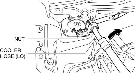
1. Remove the installation nut for the cooler hose (LO) bracket and set the cooler hose (LO) aside. (See REFRIGERANT LINE REMOVAL/INSTALLATION).
2. Remove in the order indicated in the table.
3. Install in the reverse order of removal.
4. Add brake fluid, bleed the brakes, and inspect for leakage after the installation has been completed. (See BRAKE FLUID AIR BLEEDING).
5. Switch the ignition to ON or start the engine, and maintain this condition for approx. 30 s to allow the DSC HU/CM automatic configuration to be performed.
6. Perform the DSC sensor initialization procedures. (See DSC SENSOR INITIALIZATION PROCEDURE).
7. Perform the DTC inspection using the M-MDS. (See ON-BOARD DIAGNOSIS [DYNAMIC STABILITY CONTROL (DSC)] ).
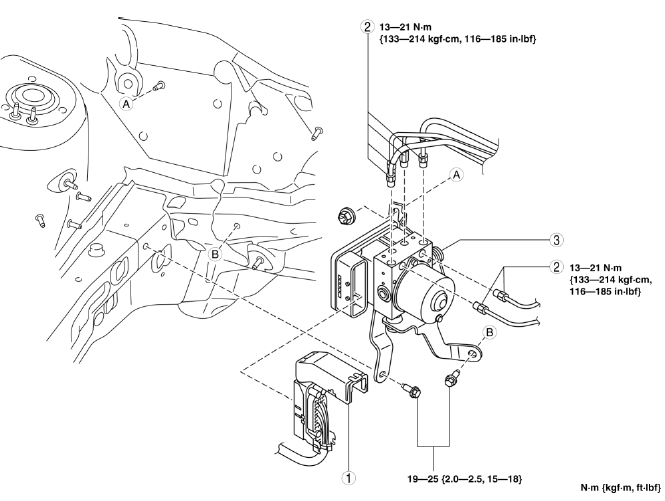
- Connector
- Brake pipe
- DSC HU/CM component
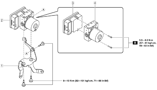
- Bracket
- DSC HU/CM
- DSC CM
- DSC HU
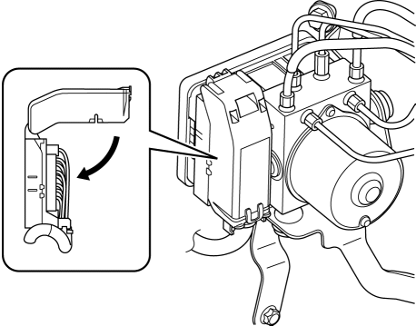
Connector Removal Note
1. Pull the connector cover up in the direction of the arrow while pressing the connector cover tab.
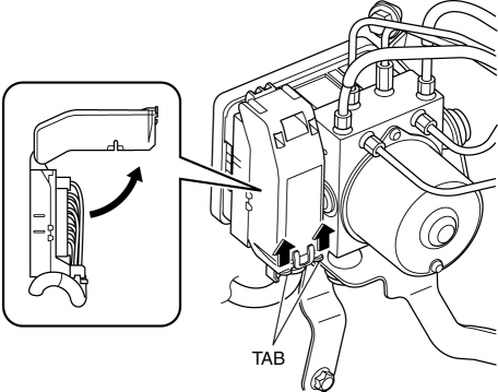
2. Pull the connector toward the vehicle left ward and remove it.
CAUTION:
- If sand or other particles get into the connector cover, it may be difficult to remove. In order not to damage the connector, be careful not to use excessive force removing the cover.
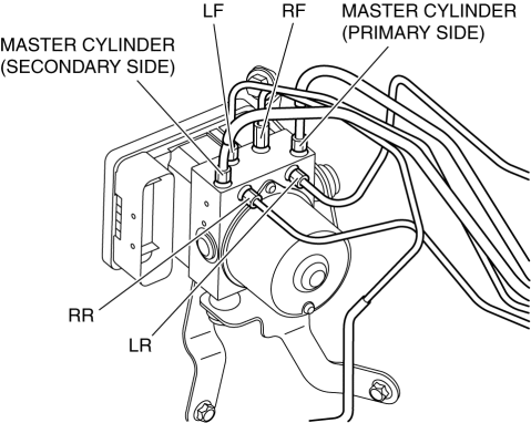
Brake Pipe Removal Note
1. Place an alignment mark on the brake pipe and DSC HU/CM.
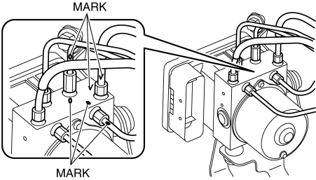
2. Affix protective tape to the connector to prevent brake fluid from entering.
3. Remove the brake pipe.
4. Adhere protective tape to the installation area of the DSC HU/CM brake pipe to prevent foreign material penetration.
Brake Pipe Installation Note
1. Align the marks made before removal and install the brake pipe into the DSC HU/CM referring to the figure.
Connector Installation Note
1. After connecting the connector, verify that the connector cover is completely pushed in.
DSC SENSOR INITIALIZATION PROCEDURE
WARNING:
- If the initialization procedure is not completed, the DSC will not operate properly and it might cause an unexpected accident. Therefore, after replacing or removing the DSC HU/CM or SAS control module, make sure to perform the initialization procedure to insure proper DSC operation.
1. Inspect the wheel alignment and the tire pressure.
- If there is any malfunction, adjust the applicable part.
2. Park the vehicle on level ground.
3. Switch the ignition to off.
4. Connect the M-MDS (IDS) to DLC-2.
5. After the vehicle is identified, select the following items from the initial screen of the IDS.
- Select "Chassis".
- Select "ABS/DSC".
- Select "Sensor Initialization".
6. Then, select an item from the screen menu.
- "Brake Fluid Pressure Sensor"
- "Lateral Acceleration Sensor"
7. Perform the procedure according to the directions on the screen.
8. Drive the vehicle.
9. After 5 min or more of driving, verify that the DSC system is normal.
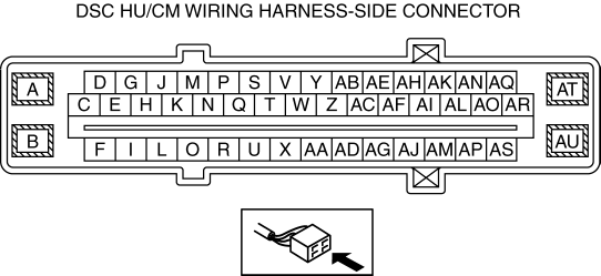
DSC HU/CM INSPECTION
1. Disconnect the DSC HU/CM connector. (See DSC HU/CM REMOVAL/INSTALLATION).
2. Connect the negative battery cable. (See BATTERY REMOVAL/INSTALLATION).
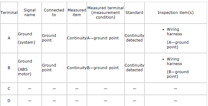
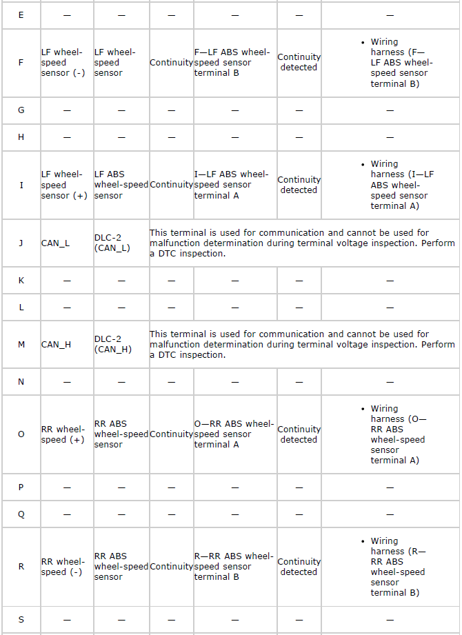
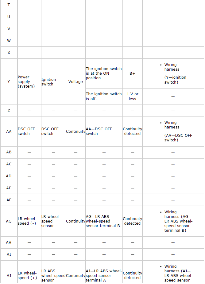
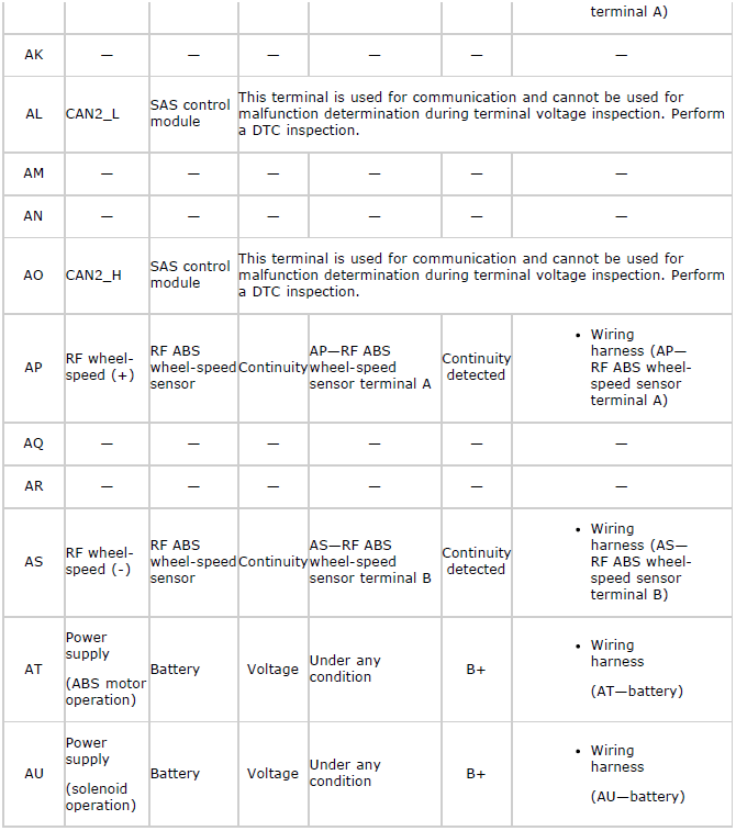
3. Attach the tester lead to the DSC HU/CM wiring harness-side connector and inspect the voltage, continuity, or resistance according to the standard (reference value) in the table below.
Standard (Reference)
FRONT ABS WHEEL-SPEED SENSOR REMOVAL/INSTALLATION
1. Remove in the order indicated in the table.
2. Install in the reverse order of removal.
3. After installation, verify that there is no twisting in the ABS wheel-speed sensor.
- Connector
- Front ABS wheel-speed sensor
- Clip
Connector Removal Note
1. Peel back the mudguard and disconnect the connector and ABS wheel-speed sensor wiring harness clip (vehicle side).
Front ABS Wheel-Speed Sensor Removal Note
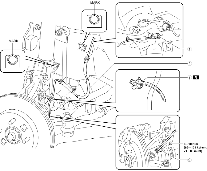
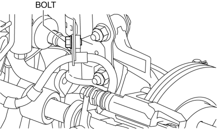
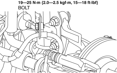
1. Remove the brake hose installation bolt shown in the figure, then remove the brake hose bracket from the shock absorber.
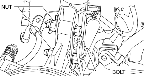
2. Remove the ABS wheel-speed sensor installation bolt, then remove the ABS wheel-speed sensor from the steering knuckle.
3. Remove the bolts and nuts shown in the figure, then disconnect the steering knuckle from the shock absorber.
4. While pressing the tabs (2 locations) of the ABS wheel-speed sensor wiring harness clip (shock absorber side), remove the ABS wheel-speed sensor wiring harness from the shock absorber.
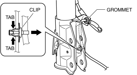
5. Remove the ABS wheel-speed sensor wiring harness grommet from the shock absorber.
6. Remove the ABS wheel-speed sensor.
7. Install the steering knuckle to the shock absorber, insert the bolts from the direction shown as follows, then tighten them to the specified torque.
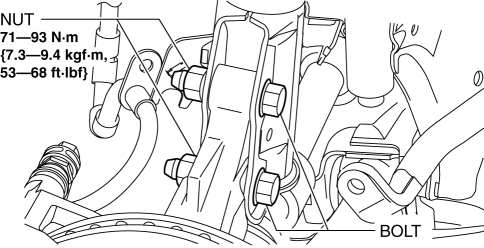
- Vehicle left side: Insert the bolts from the vehicle rear.
- Vehicle right side: Insert the bolts from the vehicle front.
8. Install the brake hose bracket to the shock absorber, then tighten the bolt to the specified torque.
Clip Removal Note
NOTE:
- Do not remove the clip except when replacing it.
1. Cut the band area of the clip, then remove the clip from the ABS wheel-speed sensor.
CAUTION:
- Be careful not to damage the ABS wheel-speed sensor when cutting the band area of the clip.
Clip Installation Note
1. Install the clip to the ABS wheel-speed sensor as shown in the figure.
2. Cut the remaining band of the clip.
FRONT ABS WHEEL-SPEED SENSOR INSPECTION
Sensor Output Value Inspection
CAUTION:
- Performing the resistance inspection using a tester may cause damage to the ABS wheel-speed sensor internal circuit. Be sure to use the M-MDS to inspect the ABS wheel-speed sensor.
1. Switch the ignition to off.
2. Connect the M-MDS to the DLC-2.
3. Select the following PIDs using the M-MDS:
- WSPD_LF (LF wheel-speed sensor)
- WSPD_RF (RF wheel-speed sensor)
4. Start the engine and drive the vehicle.
5. Verify that the display of the M-MDS shows the same value as the speedometer.
- If there is any malfunction, replace the ABS wheel-speed sensor.
Installation Visual Inspection
1. Inspect the following items:
- If there is any malfunction, replace the applicable part.
- Is there any looseness or play?
- Has the sensor been deformed?
Clearance Inspection
Preparation prior to inspection
1. Remove the ABS wheel-speed sensor. (See FRONT ABS WHEEL-SPEED SENSOR REMOVAL/INSTALLATION).
2. Remove the wheel hub, steering knuckle component. (See WHEEL HUB, STEERING KNUCKLE REMOVAL/INSTALLATION).
3. Install the ABS wheel-speed sensor to the removed wheel hub, steering knuckle component, and tighten to the specified torque.
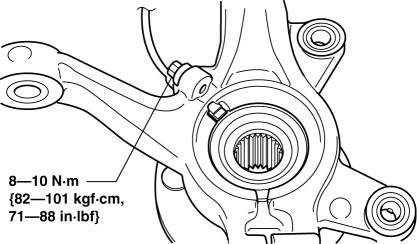
Tightening torque
- 8-10 N*m {82-101 kgf*cm, 71-88 in*lbf}
Clearance Inspection
1. Measure the gap between the ABS sensor rotor and ABS wheel-speed sensor using a feeler gauge.
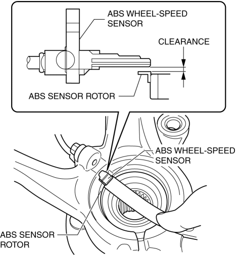
- If not within the specification, verify the following items and repair
or replace if necessary.
- Is there deformation or damage to the ABS sensor rotor?
- Is there deformation or damage to the ABS wheel speed sensor?
- Is there foreign material adhering?
Clearance
- 0.5-1.3 mm {0.02-0.05 in}
Servicing after inspection
1. Remove the ABS wheel-speed sensor from the wheel hub, steering knuckle component.
2. Install the wheel hub, steering knuckle component. (See WHEEL HUB, STEERING KNUCKLE REMOVAL/INSTALLATION).
3. Install the ABS wheel-speed sensor. (See FRONT ABS WHEEL-SPEED SENSOR REMOVAL/INSTALLATION).
4. Inspect the front wheel alignment. (See FRONT WHEEL ALIGNMENT).
REAR ABS WHEEL-SPEED SENSOR REMOVAL/INSTALLATION
1. Remove the rear scuff plate. (See REAR SCUFF PLATE REMOVAL/INSTALLATION).
2. Remove the rear seat cushion. (See REAR SEAT CUSHION REMOVAL/INSTALLATION).
3. Remove the rear seat back. (See REAR SEAT BACK REMOVAL/INSTALLATION).
4. Remove the trunk end trim. (See TRUNK END TRIM REMOVAL/INSTALLATION).
5. Remove the trunk side trim. (See TRUNK SIDE TRIM REMOVAL/INSTALLATION).
6. Disconnect the rear ABS wheel-speed sensor connector.
7. Press the rear ABS wheel-speed sensor tabs and press out the sensor toward the outside of the vehicle.
8. Remove in the order indicated in the table.
9. Install in the reverse order of removal.
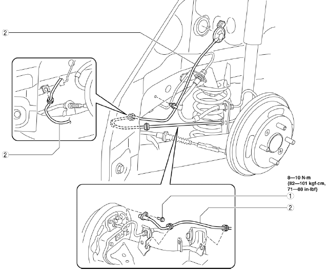
- Bolt
- Rear ABS wheel-speed sensor
REAR ABS WHEEL-SPEED SENSOR INSPECTION
Installation Visual Inspection
1. Inspect the following items:
- If there is any malfunction, replace the applicable part.
- Is there looseness or play in the sensor installation?
- Has the sensor been deformed?
- Is there deformation of or damage to the ABS sensor rotor?
Clearance inspection
1. Remove the rear ABS wheel-speed sensor.
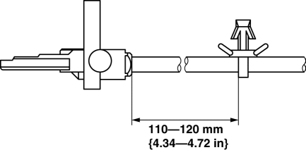
2. Measure the distance between the rear ABS wheel-speed sensor installation surface and the ABS sensor rotor. This is dimension A.
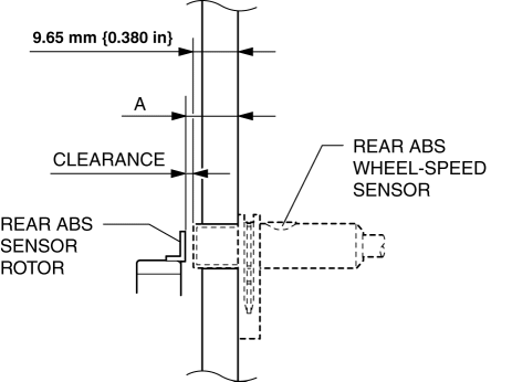
3. Calculate the clearance between the rear ABS wheel-speed sensor and the ABS sensor rotor using the following formula:
- Clearance (mm {in}) = A-9.525 {0.3750}
4. Verify that the clearance between the ABS sensor rotor and the rear ABS wheel-speed sensor is as indicated below.
- If there is any malfunction, verify the installation condition and replace if necessary.
Clearance
- 0.40-1.15 mm {0.016-0.045 in}
Sensor Output Value Inspection
CAUTION:
- Performing the resistance inspection using a tester may cause damage to the ABS wheel-speed sensor internal circuit. Be sure to use the M-MDS to inspect the ABS wheel-speed sensor.
1. Switch the ignition to off.
2. Connect the M-MDS to the DLC-2.
3. Select the following PIDs using the M-MDS:
- WSPD_LR (LR wheel-speed sensor)
- WSPD_RR (RR wheel-speed sensor)
4. Start the engine and drive the vehicle.
5. Verify that the display of the M-MDS shows the same value as the speedometer.
- If there is any malfunction, replace the ABS wheel-speed sensor.
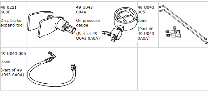
BRAKE FLUID PRESSURE SENSOR INSPECTION
1. Switch the ignition to off.
2. Disconnect the brake pipe flare nut.
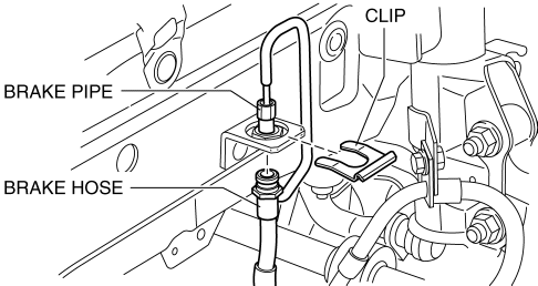
3. Remove the clip and disconnect the brake hose.
4. Install the SSTs to the brake pipe as shown in the figure.
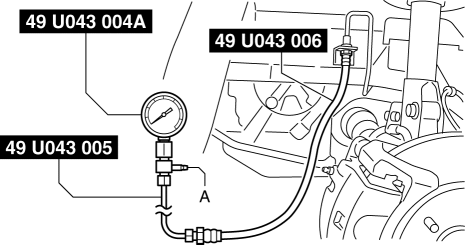
5. Perform air bleeding of the SST and brake line from bleeder screw A.
6. Connect the M-MDS to the DLC-2.
7. Select the "MCYLI_P" PID. (See ON-BOARD DIAGNOSIS [DYNAMIC STABILITY CONTROL (DSC)] ).
8. Start the engine.
9. Depress the brake pedal, and verify that the fluid pressure value of the SST (gauge) and the value shown on the M-MDS are equal.
- If the fluid pressure values are different, replace the DSC HU/CM. (See DSC HU/CM REMOVAL/INSTALLATION).
10. Remove the SSTs after the inspection and install the brake hose, clip and brake pipe to their original positions. (See BRAKE HOSE (FRONT) REMOVAL/INSTALLATION).
11. Perform air bleeding of the brake line. (See BRAKE FLUID AIR BLEEDING).
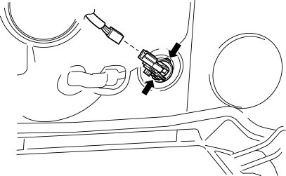
DSC OFF SWITCH REMOVAL/INSTALLATION
1. Remove the switch panel in the direction of the arrow shown in the figure.
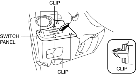
2. Disconnect the connector.
3. Press the tabs in the direction of the arrow (1) shown in the figure and remove the DSC OFF switch in the direction of the arrow (2).
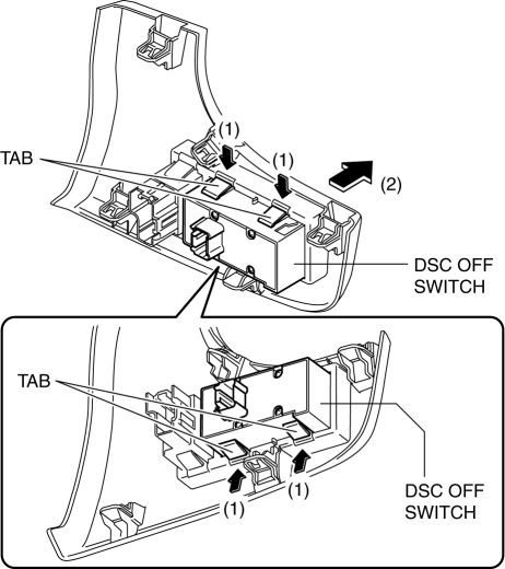
4. Install in the reverse order of removal.
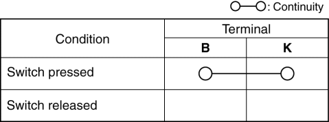
DSC OFF SWITCH INSPECTION
1. Remove the DSC OFF switch. (See DSC OFF SWITCH REMOVAL/INSTALLATION).
2. Verify that the continuity between the DSC OFF switch terminals is as indicated in the table.
- If not as indicated in the table, replace the DSC OFF switch.
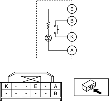
3. Apply battery voltage to DSC OFF switch terminal E, and connect terminal A to ground.
4. Verify that the LED illuminates.
- If there is any malfunction, replace the DSC OFF switch.
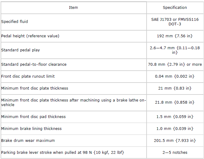
BRAKES TECHNICAL DATA
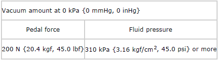
Standard power brake unit non-servo operation
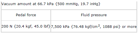
Standard power brake unit servo operation
BRAKES SST