Mazda 2: Brake Pedal
BRAKE PEDAL INSPECTION
Pedal Height Inspection
1. Measure the distance from the steering shaft cover to the center of the upper surface of the pedal pad and verify that it is as specified.
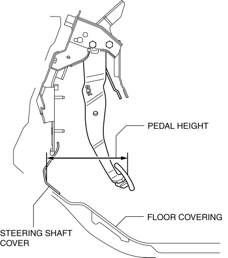
- If not within the specification, replace the pedal component.
Pedal height (reference value)
- 192 mm {7.56 in}
Pedal play inspection
1. Pump the pedal several times to release the vacuum in the power brake unit.
2. Gently depress the pedal by hand and measure the pedal play.
- If not within the specification, inspect the wear of the clevis pin. Replace it if there is any malfunction.
Standard pedal play
- 2.6-4.7 mm {0.11-0.18 in}
NOTE:
- If there is no malfunction in the clevis pin, there is a possibility that the power brake unit has some malfunction. Verify that there are no malfunctions and perform part replacement if necessary.
Pedal-to-floor Clearance Inspection
1. Start the engine and depress the brake pedal with a force of 147 N {15.0 kgf, 33.0 lbf}.
2. Measure the distance between the floor panel and the pedal pad center and verify that the dimensions are as shown in the figure.
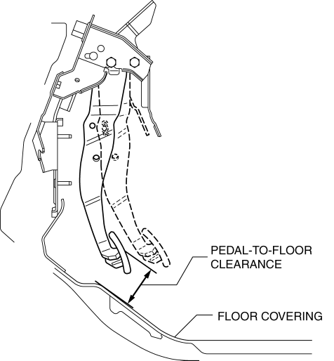
- If the pedal-to-floor clearance is less than the specification, inspect for air in the brake system.
Standard pedal-to-floor clearance
- 70.8 mm {2.79 in} or more
BRAKE PEDAL REMOVAL/INSTALLATION
CAUTION:
- The clearance between the brake switch and the brake pedal of MTX vehicles is automatically adjusted to the correct amount when the brake switch is inserted into the installation hole on the brake pedal and rotated to fix it in place. If the brake switch is not properly installed, the clearance may be incorrect, causing a brake light malfunction. Therefore, always verify that the brake pedal is properly installed and fully released before installing the brake switch to the pedal.
- The clearance between the brake switch and the brake pedal of ATX vehicles is automatically adjusted to the correct amount when the connector is connected after the brake switch has been properly installed. If the brake switch is not properly installed or the connector is connected before installation, the clearance may be incorrect, causing a brake light malfunction. Therefore, always verify that the brake switch is properly installed before connecting the connector.
- Once the brake switch clearance has automatically been adjusted, it cannot be adjusted again. Therefore, always replace the brake switch with a new one when replacing the power brake unit or the pedal, or when performing any procedure that changes the pedal stroke.
1. Remove the accelerator pedal. (See ACCELERATOR PEDAL REMOVAL/INSTALLATION).
2. Remove in the order indicated in the table.
3. Install in the reverse order of removal.
CAUTION:
- When replacing the brake pedal component of ATX vehicles, see the Interlock Cable Installation Note to prevent incorrect installation could result. (See AUTOMATIC TRANSAXLE SHIFT MECHANISM REMOVAL/INSTALLATION).
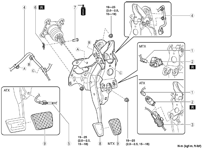
- Brake switch connector
- Brake switch
- Lock unit
- Wiring harness
- Interlock cable
- Snap pin
- Clevis pin
- Brake pedal
- Pedal pad
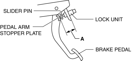
Lock Unit Removal Note
1. Before removing the lock unit, measure length A (between lock unit and pedal arm stopper plate) and note it down for reference in installation.
Brake Pedal Removal Note
1. Remove the brake pedal as shown in the figure.
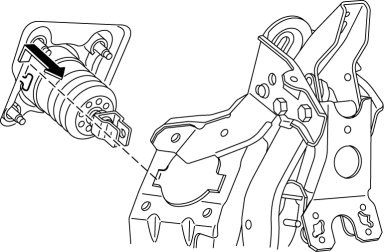
NOTE:
- If the brake pedal is difficult to remove, move the power brake unit component a little toward the vehicle front while being careful of the brake pipe.
Brake Pedal Installation Note
1. Install the brake pedal as shown in the figure.
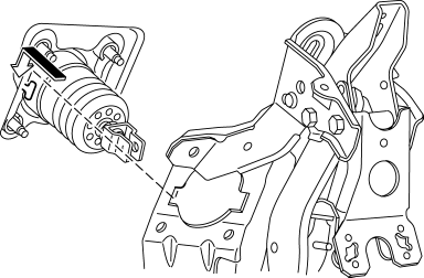
NOTE:
- If the brake pedal is difficult to remove, move the power brake unit component a little toward the vehicle front while being careful of the brake pipe.
Lock Unit Installation Note
1. Verify that length A measured at installation has not changed and install the lock unit.

- If length A has changed, replace the interlock cable with a new one. (See AUTOMATIC TRANSAXLE SHIFT MECHANISM REMOVAL/INSTALLATION).
Brake Switch Installation Note (MTX)
1. Inspect the brake pedal. (See BRAKE PEDAL INSPECTION).
2. With the brake pedal fully released, insert a new brake switch into the installation hole on the brake pedal.
3. Secure the brake switch by turning it counterclockwise 45

