Mazda 2: Master Cylinder
MASTER CYLINDER REMOVAL/INSTALLATION
CAUTION:
- When removing/installing the master cylinder, avoid touching the primary
piston with your hand when not necessary.
Otherwise, it could damage the master cylinder.
1. Remove the battery. (See BATTERY REMOVAL/INSTALLATION).
2. Remove in the order indicated in the table.
3. Install in the reverse order of removal.
4. Add brake fluid, bleed the brakes, and inspect for leakage after the installation has been completed. (See BRAKE FLUID AIR BLEEDING).
- Brake fluid level sensor connector
- No.2 reserve tank, cap
- Reserve tank hose
- Reserve tank hose (MTX)
- Brake pipe
- Master cylinder component
Reserve Tank Hose Removal Note
1. Move the clip upward.
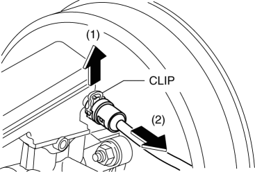
2. Disconnect the reserve tank hose.
Reserve Tank Hose Installation Note
1. Press the clip in after the reserve hose is inserted completely.
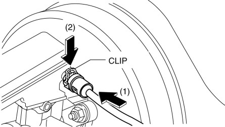
2. Verify that the reserve tank hose is securely installed by pulling it, and reinsert into the reserve tank.
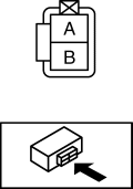
BRAKE FLUID LEVEL SENSOR INSPECTION
1. Disconnect the connector from the brake fluid level sensor.
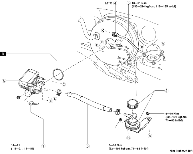
2. Inspect for continuity between the brake fluid level sensor terminals.
- If not as indicated in the table, replace the Master cylinder component.