Mazda 2: Power Brake Unit
POWER BRAKE UNIT INSPECTION
NOTE:
- The following inspection methods are simple inspection methods to judge the function of the power brake unit.
- If there is any malfunction in the power brake unit, replace the power brake unit as a single component.
Without Using SST
Operation inspection
1. Depress the pedal several times with the engine stopped.
2. With the pedal depressed, start the engine.
3. If the pedal moves down slightly immediately after engine start, the unit is normal.
Vacuum function inspection
1. Start the engine.
2. Stop the engine after driving the vehicle for 1-2 min.
3. Depress the pedal with normal force.
4. If the first pedal stroke is long and becomes shorter with subsequent strokes, the unit is normal.
- If a malfunction is found, inspect for damage to or improper installation of the check valve and vacuum hose. After repairing, inspect again.
Vacuum loss function inspection
1. Start the engine.
2. Depress the pedal with normal force.
3. Stop the engine under this condition.
4. Hold the pedal depressed for approx. 30 s.
5. If the pedal height does not change during this time, the unit is normal.
When using SST
NOTE:
- When performing the inspection using the SST, inspect the brake pipe on the left or right front wheel.
- The following procedure and figures show the inspection for the brake pipe on the left front wheel.
Preparation before inspection
1. Disconnect the brake pipe flare nut.
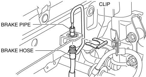
2. Remove the clip and disconnect the brake hose.
3. Install the SSTs to the brake pipe as shown in the figure.
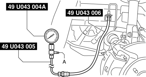
4. Perform air bleeding of the SST and brake line from bleeder screw A.
5. Install the pedal force gauge to the brake pedal.
6. Connect the vacuum piping to the vacuum gauge.
Checking for vacuum loss (loaded condition)
1. Start the engine.
2. Depress the brake pedal with a force of 200 N {20.4 kgf, 45.0 lbf}.
3. Stop the engine when the vacuum gauge reading reaches 68 kPa {510 mmHg, 20 inHg} with the pedal depressed.
4. Measure the amount of vacuum decrease for 15 s immediately after stopping the engine.
5. If the gauge indicates a drop of 3.3 kPa {25 mmHg, 0.97 inHg} or less, the unit is normal.
Non-servo operation inspection
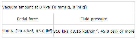
1. If the pedal force and fluid pressure correlation is within the specification with the engine stopped and a vacuum amount of 0 kPa {0 mmHg, 0 inHg}, the system is normal.
Standard power brake unit non-servo operation
Servo operation inspection
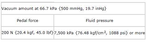
1. Start the engine and depress the brake pedal when the vacuum reaches 66.7 kPa {500 mmHg, 19.7 inHg}.
2. At this time, apply the indicated pedal force and if the fluid pressure is within the specification, the unit is normal.
Standard power brake unit servo operation
Procedure after inspection
1. Remove the SST after the inspection and install the brake hose, clip and brake pipe to their original positions. (See BRAKE HOSE (FRONT) REMOVAL/INSTALLATION).
2. Perform air bleeding of the brake line. (See BRAKE FLUID AIR BLEEDING).
POWER BRAKE UNIT REMOVAL/INSTALLATION
CAUTION:
- Once the brake switch clearance has automatically been adjusted, it cannot be adjusted again. Therefore, always replace the brake switch with a new one when replacing the power brake unit or when performing any procedure that changes the pedal stroke.
1. Remove the battery and battery tray. (See BATTERY REMOVAL/INSTALLATION).
2. Remove the windshield wiper arm and blade. (See WINDSHIELD WIPER ARM AND BLADE REMOVAL/INSTALLATION).
3. Remove the front fender molding. (See FRONT FENDER PANEL REMOVAL/INSTALLATION).
4. Remove the cowl grille. (See COWL GRILLE REMOVAL/INSTALLATION).
5. Remove the windshield wiper motor. (See WINDSHIELD WIPER MOTOR REMOVAL/INSTALLATION).
6. Remove the cowl panel. (See COWL PANEL REMOVAL/INSTALLATION).
7. Remove the master cylinder. (See MASTER CYLINDER REMOVAL/INSTALLATION).
8. Remove in the order indicated in the table.
9. Remove the brake switch. (See BRAKE PEDAL REMOVAL/INSTALLATION).
10. Install in the reverse order of removal.
11. After installation, inspect the brake pedal. (See BRAKE PEDAL INSPECTION).
12. Perform the shift-lock and key interlock inspections with the ATX vehicles. (See SHIFT-LOCK SYSTEM INSPECTION). (See KEY INTERLOCK SYSTEM INSPECTION).
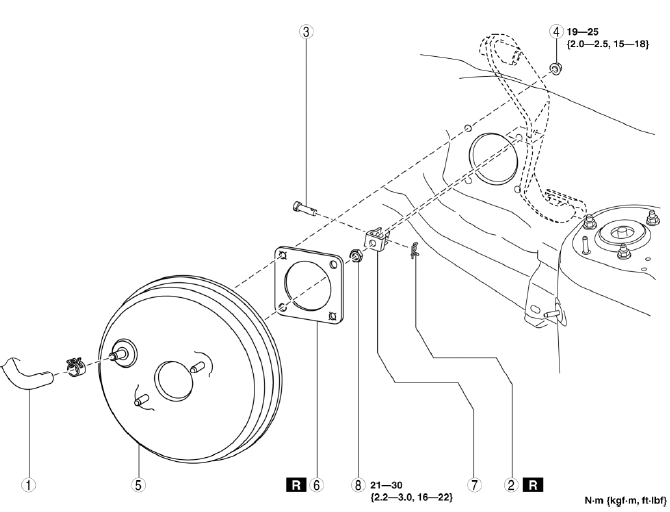
- Vacuum hose
- Snap pin
- Clevis pin
- Nut
- Power brake unit
- Gasket
- Fork
- Locknut
Fork Installation Note
1. Install the fork as shown in the figure.
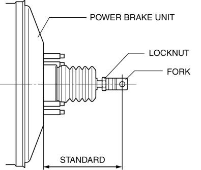
Standard
- 117.5-118.5 mm {4.626-4.665 in}
FRONT BRAKE (DISC) INSPECTION
Brake Judder Repair Hints
Description
1. Brake judder concern has the following 3 characteristics:
Steering wheel vibration
1. The steering wheel vibrates in the rotation direction. This characteristic is most noticeable when applying brakes at a vehicle speed of 100-140 km/h {62.2-86.9 mph}.
Floor vibration
1. When applying the brakes, the vehicle body shakes back and forth. The seriousness of the shaking is not influenced by vehicle speed.
Brake pedal vibration
1. When applying the brakes, a pulsating force tries to push the brake pad back. The pulsation is transmitted to the brake pedal.
2. The following are the main possible causes of brake judder:
Due to an excessive runout (side-to-side wobble) of the disc plate, the thickness of the disc plate is uneven.
1. If the runout is more than 0.04 mm {0.002 in} at the position 10 mm {0.39 in} from the disc plate edge, uneven wear occurs on the disc plate because the pad contacts the plate unevenly.
2. If the runout is less than 0.04 mm {0.002 in}, uneven wear does not occur.
The disc plate is deformed by heat.
1. Repeated panic braking may raise the temperature in some portions of the disc plate by approx. 1,000

