Mazda 2: Manifold Absolute Pressure (MAP) Sensor
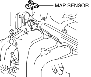
MANIFOLD ABSOLUTE PRESSURE (MAP) SENSOR REMOVAL/INSTALLATION
1. Disconnect the negative battery cable.
2. Remove the fresh-air duct and the air cleaner as a single unit. (See INTAKE-AIR SYSTEM REMOVAL/INSTALLATION).
3. Disconnect the MAP sensor connector.
4. Remove the MAP sensor

5. Install in the reverse order of removal.
MANIFOLD ABSOLUTE PRESSURE (MAP) SENSOR INSPECTION
1. Connect the M-MDS to the DLC-2.
2. Switch the ignition to ON.
3. Verify that the voltage (M-MDS PID: MAP) within the specification. (See PCM INSPECTION).
- If not as specified, replace the MAP sensor. (See MANIFOLD ABSOLUTE PRESSURE (MAP) SENSOR REMOVAL/INSTALLATION).
BAROMETRIC PRESSURE (BARO) SENSOR REMOVAL/INSTALLATION
CAUTION:
- The BARO sensor cannot be removed as a single unit. When replacing the BARO sensor, replace it together with the PCM as a single unit.
1. Remove the PCM. (See PCM REMOVAL/INSTALLATION).
BAROMETRIC PRESSURE (BARO) SENSOR INSPECTION
CAUTION:
- The BARO sensor cannot be removed as a single unit. When replacing the BARO sensor, replace it together with the PCM as a single unit.
1. Connect the M-MDS to the DLC-2.
2. Switch the ignition to ON.
3. Verify that the BARO sensor output voltage (M-MDS PID: BARO) is within the specification.
(See PCM INSPECTION).
- If not as specified, replace the PCM.
(See PCM REMOVAL/INSTALLATION).
THROTTLE POSITION (TP) SENSOR REMOVAL/INSTALLATION
CAUTION:
- The TP sensor cannot be removed as a single unit. When replacing the TP sensor, replace it together with the throttle body as a single unit.
1. Remove the throttle body. (See INTAKE-AIR SYSTEM REMOVAL/INSTALLATION).
THROTTLE POSITION (TP) SENSOR INSPECTION
CAUTION:
- This inspection procedure cannot be completed correctly if the APP sensor has a malfunction. Before performing this procedure, verify that any one of the DTCs related to the APP sensor is not detected.
- The TP sensor cannot be removed as a single unit. When replacing the TP sensor, replace it together with the throttle body as a single unit.
1. Connect the M-MDS to the DLC-2.
2. Switch the ignition to ON.
3. Verify that the TP sensor output voltage (M-MDS PID: TP1, TP2) is within the specification. (See PCM INSPECTION).
- If not as specified, replace the throttle body.
(See INTAKE-AIR SYSTEM REMOVAL/INSTALLATION).
ACCELERATOR PEDAL POSITION (APP) SENSOR INSPECTION
CAUTION:
- The APP sensor cannot be removed as a single unit. When replacing the APP sensor, replace it together with the accelerator pedal as a single unit.
1. Connect the M-MDS to the DLC-2.
2. Switch the ignition to ON.
3. Verify that the APP sensor output voltage (PID: APP1, APP2) increases according to the increase in the accelerator opening angle when the accelerator opening angle is gradually increased.
- If verified, go to the next step.
- If not as verified, replace the accelerator pedal. (See ACCELERATOR PEDAL REMOVAL/INSTALLATION).
4. Verify that the APP sensor output voltage (PID: APP1, APP2) is within the specification when the accelerator pedal is depressed and not depressed.
- If not as specified, replace the accelerator pedal. (See ACCELERATOR PEDAL REMOVAL/INSTALLATION).
ACCELERATOR PEDAL POSITION (APP) SENSOR REMOVAL/INSTALLATION
CAUTION:
- The APP sensor cannot be removed as a single unit. When replacing the APP sensor, replace it together with the accelerator pedal as a single unit.
1. Remove the accelerator pedal. (See ACCELERATOR PEDAL REMOVAL/INSTALLATION).

