Mazda 2: Rear Axle
REAR AXLE LOCATION INDEX
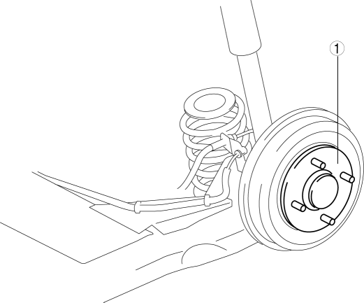
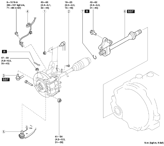
- Rear axle component
REAR AXLE INSPECTION
Wheel Bearing Play Inspection
1. Inspect the wheel bearing play in the same way as the front axle. (See WHEEL HUB, STEERING KNUCKLE INSPECTION).
- If it exceeds the specification, replace the wheel hub component. (See WHEEL HUB COMPONENT REMOVAL/INSTALLATION).
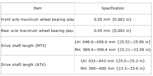
Rear axle maximum wheel bearing play
- 0.05 mm {0.002 in}
WHEEL HUB COMPONENT REMOVAL/INSTALLATION
CAUTION:
- Performing the following procedures without first removing the ABS wheel-speed sensor may possibly cause an open circuit in the wiring harness if it is pulled by mistake. Before performing the following procedures, disconnect the ABS wheel-speed sensor connector (body side) and fix the wiring harness to an appropriate place where it will not be pulled by mistake while servicing the vehicle.
1. Remove in the order indicated in the table.
2. Install in the reverse order of removal.
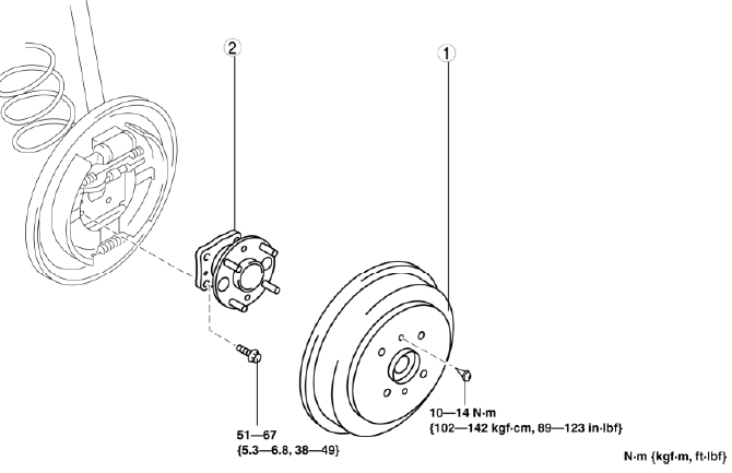
- Brake drum
- Wheel hub component
REAR WHEEL HUB BOLT REPLACEMENT
1. Remove the brake drum. (See REAR BRAKE (DRUM) REMOVAL/INSTALLATION).
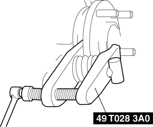
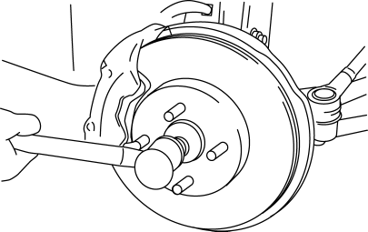
2. Remove the wheel hub bolt using the SST as shown in the figure.
3. Place a new wheel hub bolt in the wheel hub.
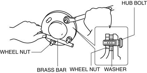
4. Install the wheel hub by placing a proper sized washer on the hub, and tightening the nut as shown in the figure.
DRIVE SHAFT LOCATION INDEX
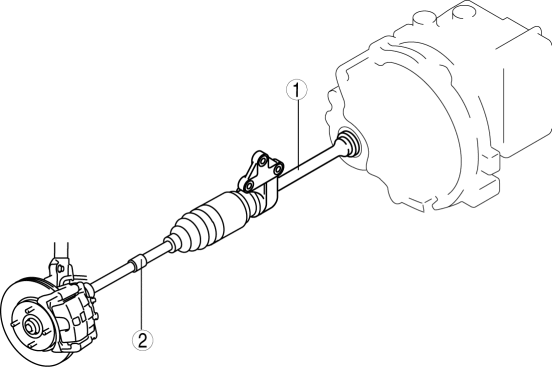
- Joint shaft
- Drive shaft
DRIVE SHAFT INSPECTION
1. Inspect the connections for any looseness.
- If there is any malfunction, tighten or replace the part.
2. Inspect the boot for damage and cracks.
- If there is any malfunction, replace the part.
3. Inspect the drive shaft for bends, cracks, and wear in the joint or splines.
- If there is any malfunction, replace the part.
DRIVE SHAFT REMOVAL/INSTALLATION
1. Drain the transaxle oil or ATF. (See TRANSAXLE OIL REPLACEMENT). (See AUTOMATIC TRANSAXLE FLUID (ATF) REPLACEMENT).
2. Remove in the order indicated in the table.
3. Install in the reverse order indicated in the table.
4. Add the transaxle oil or ATF. (See TRANSAXLE OIL REPLACEMENT). (See AUTOMATIC TRANSAXLE FLUID (ATF) REPLACEMENT).
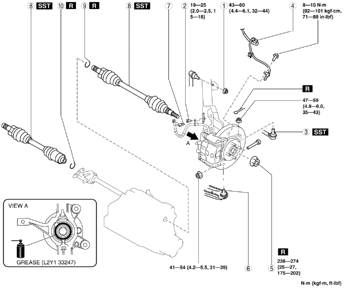
- Nut (stabilizer control link upper side)
- Bolt (brake hose bracket)
- Tie-rod end
- ABS wheel-speed sensor
- Locknut
- Front lower arm ball joint
- Clip
- Drive shaft
- Drive shaft clip
- Joint shaft clip
ABS Wheel-Speed Sensor Removal Note
1. Remove the ABS wheel-speed sensor installation bolt, then remove the ABS wheel-speed sensor from the steering knuckle.
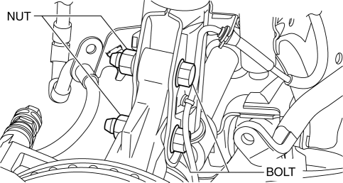
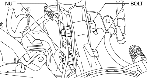
2. Remove the bolts and nuts shown in the figure, then disconnect the steering knuckle from the shock absorber.
3. While pressing the tabs (2 locations) of the ABS wheel-speed sensor wiring harness clip, remove the ABS wheel-speed sensor wiring harness from the shock absorber.
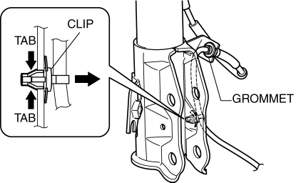
4. Remove the ABS wheel-speed sensor wiring harness grommet from the shock absorber.
5. Move the ABS wheel-speed sensor to a place out of the way.
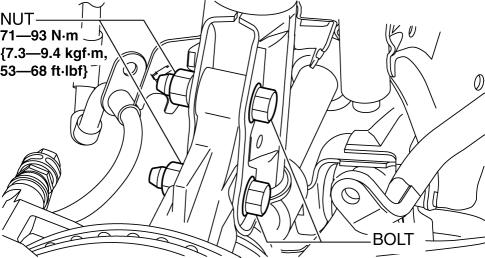
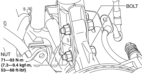
6. Install the steering knuckle to the shock absorber, insert the bolts from the direction shown as follows, then tighten them to the specified torque.
- Vehicle left side: Insert the bolts from the vehicle rear.
- Vehicle right side: Insert the bolts from the vehicle front.
Drive Shaft Removal Note
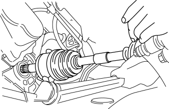
1. Install a spare nut onto the drive shaft so that the nut is flush with the end of the drive shaft.
2. Tap the nut with a copper hammer to loosen the drive shaft from the front wheel hub.
3. Separate the drive shaft from the wheel hub.
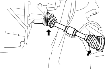
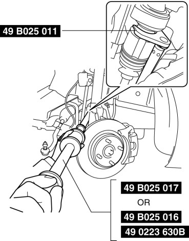
4. Separate the LH drive shaft from the transaxle using the SSTs as shown in the figure.
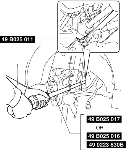
CAUTION:
- The sharp edges of the drive shaft can slice or puncture the oil seal. Be careful when removing the drive shaft from the transaxle.
5. Remove the RH drive shaft from the joint shaft using the SSTs.

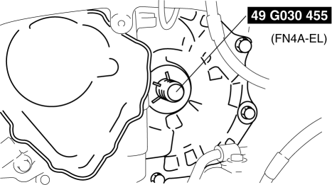
6. Install the SST to the transaxle after the drive shaft is removed.
Drive Shaft Clip Installation Note
1. Install a new clip onto the joint shaft with the opening facing upward. Ensure that the diameter of the clip does not exceed the specification on installation.
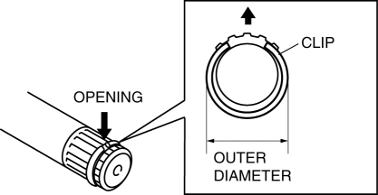
Outer diameter
- ATX: 29.5 mm {1.16 in}
- MTX: 27.5 mm {1.08 in}
Drive Shaft Installation Note
LH side
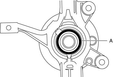
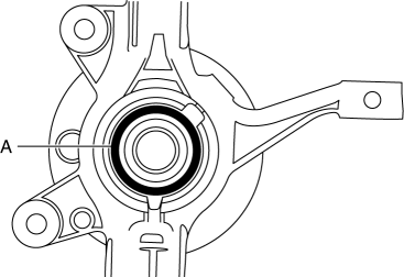
1. Apply grease (L2Y1 33247) to the wheel bearing inner race and drive shaft contact surface (Area A in figure).
2. Insert the drive shaft into the wheel hub.
3. Apply transaxle oil or ATF to the oil seal lip.
4. Push the drive shaft into the transaxle.
CAUTION:
- The sharp edges of the joint shaft can slice or puncture the oil seal. Be careful when installing the joint shaft to the transaxle.
5. After installation, pull the transaxle side outer ring forward to confirm that the drive shaft is securely held by the clip.
RH side
1. Apply grease (L2Y1 33247) to the wheel bearing inner race and drive shaft contact surface (Area A in figure).
2. Insert the drive shaft to the wheel hub.
3. Insert the drive shaft to the joint shaft.
4. After installation, pull the transaxle side outer ring forward to confirm that the drive shaft is securely held by the clip.
ABS Wheel-Speed Sensor Installation Note
1. Install the ABS wheel-speed sensor wiring harness grommet to the shock absorber as shown in the figure.
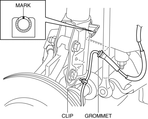
2. Install the ABS wheel-speed sensor wiring harness clip to the shock absorber.
3. Install the ABS wheel-speed sensor to the steering knuckle, then tighten the bolt (ABS wheel-speed sensor) to the specified torque.
4. Verify that the ABS wheel-speed sensor wiring harness is not twisted.
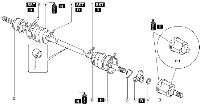
DRIVE SHAFT (MTX) DISASSEMBLY/ASSEMBLY
1. Disassemble in the order indicated in the table.
2. Assemble in the reverse order of disassembly.
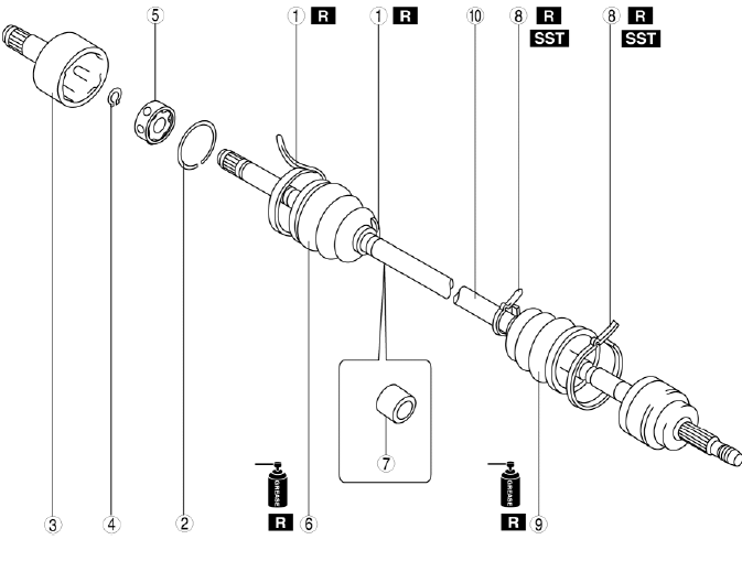
- Boot band (transaxle side)
- Clip
- Outer ring
- Snap ring
- Balls, inner ring, cage
- Boot
- Dynamic damper (if equipped)
- Boot band (wheel side)
- Boot
- Shaft and ball joint component
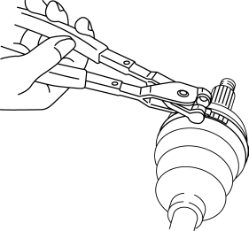
Boot Band (Wheel Side) Disassembly Note
NOTE:
- The boot band does not need to be removed unless it is being replaced.
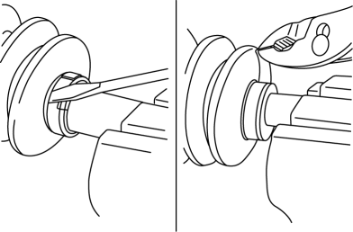
1. Remove the boot band using an end clamp plier.
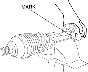
Clip Disassembly Note
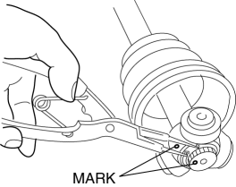
1. Mark the drive shaft and outer ring for proper assembly.
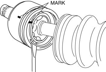
CAUTION:
- Mark with paint; do not use a punch
2. Remove the clip.
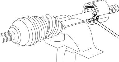
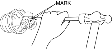
Snap Ring Disassembly Note
1. Mark the drive shaft end and inner ring for proper assembly.
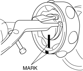
CAUTION:
- Mark with paint; do not use a punch
2. Remove the snap ring using a snap ring plier.
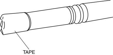
Boot Disassembly Note
NOTE:
- The wheel side boot do not need to be removed unless they are being replaced.
1. Wrap the shaft splines with tape.
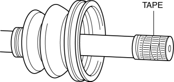
2. Remove the boot.
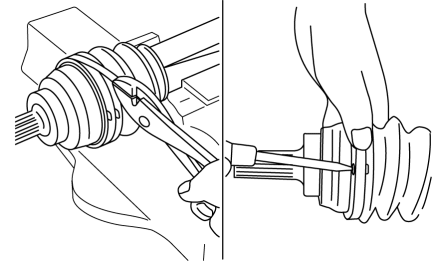
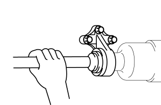
Boot Band (Transaxle Side) Disassembly Note
1. Pry up the points indicated in the figure using a plier, and remove the boot band.
Boot Assembly Note
NOTE:
- The wheel side and transaxle side boots are different. Do not install the wrong boot by mistake.
1. Fill the inside of the new dust boot (wheel side) with grease.
CAUTION:
- Do not touch the grease with your hand. Apply it from the tube to prevent foreign matter from entering the boot.
Grease amount
- 55-75 g {2.0-2.6 oz}
2. Install the boot with the splines of the shaft still wrapped in tape from disassembly.
3. Remove the tape.
Boot Band (Wheel Side) Assembly Note
Boot band (small diameter side)
1. Adjust clearance A by turning the adjusting bolt of the SST.
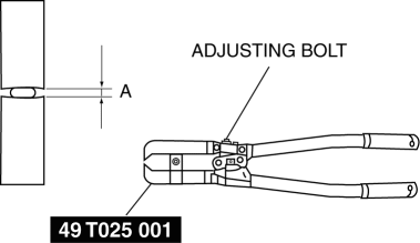
Clearance A
- 2.9 mm {0.11 in}
2. Crimp the wheel side small boot band using the SST. Verify that clearance B is within the specification.
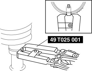
- If clearance B is more than the specification, reduce clearance A of the SST and crimp the boot again.
- If clearance B is less than the specification, replace the boot band, increase clearance A of the SST, and crimp the new boot.
Clearance B
- 2.4-2.8 mm {0.10-0.11 in}
3. Verify that the boot band does not protrude from the boot band installation area.
- If it does, replace the boot band and repeat Steps 2 and 3.
Boot band (Large diameter side)
1. Adjust clearance C by turning the adjusting bolt of the SST.
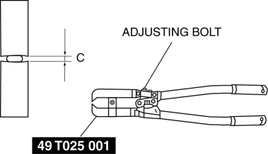
Clearance C
- 3.2 mm {0.13 in}
2. Crimp the wheel side large boot band using the SST. Verify that clearance D is within the specification.
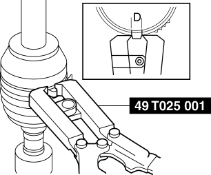
- If clearance D is more than the specification, reduce clearance C of the SST and crimp the boot again.
- If clearance D is less than the specification, replace the boot band, increase clearance C of the SST, and crimp the new boot.
Clearance D
- 2.4-2.8 mm {0.10-0.11 in}
3. Verify that the boot band does not protrude from the boot band installation area.
- If it does, replace the boot band and repeat Steps 2 and 3.
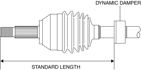
Dynamic Damper Assembly Note
1. Install the dynamic damper as shown in the figure.
Cage, Inner Ring, Balls, Snap Ring Assembly Note
1. Align the marks and install the inner ring to the shaft.
2. Install a new snap ring.
Outer Ring Assembly Note
1. Fill the outer ring and boot (transaxle side) with the specified grease.
CAUTION:
- Do not touch the grease with your hand. Apply it from the tube to prevent foreign matter from entering the boot.
Grease amount
- 50-70 g {1.8-2.4 oz}
2. Assemble the outer ring.
3. Set the drive shaft to the standard length.
Drive shaft standard length
- LH: 648.0-658.0 mm {25.52-25.90 in}
- RH: 589.4-599.4 mm {23.21-23.59 in}
4. Release any trapped air from the boots by carefully lifting up the small end of each boot with a cloth wrapped screwdriver.
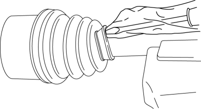
CAUTION:
- Do not let the grease leak.
- Do not damage the boot.
5. Verify that the drive shaft length is within the standard under atmospheric pressure inside the boot.
- If not within the specification, repeat the Steps 3-5.
Boot Band (Transaxle Side) Assembly Note
1. Pry up the points indicated in the figure using a plier, and tighten the boot band.
CAUTION:
- Verify that the boot band is installed into the groove securely.
DRIVE SHAFT (ATX) DISASSEMBLY/ASSEMBLY
1. Disassemble in the order indicated in the table.
2. Assemble in the reverse order of disassembly.
- Boot band (transaxle side)
- Clip
- Outer ring
- Snap ring
- Tripod joint
- Boot
- Dynamic damper
- Boot band (wheel side)
- Boot
- Shaft and ball joint component
Clip, Outer Ring Disassembly Note
1. Mark the drive shaft and outer ring.
2. Remove the clip.
3. Remove the outer ring.
Snap Ring And Tripod Joint Disassembly Note
1. Mark the shaft and tripod joint.
2. Remove the snap ring using a snap ring plier.
3. Remove the tripod joint from the shaft.
CAUTION:
- Do not tap the tripod joint with a hammer.
Boot Disassembly Note
NOTE:
- The wheel side boot do not need to be removed unless they are being replaced.
1. Wrap the shaft splines with tape.
2. Remove the boot.
Boot Assembly Note
NOTE:
- The wheel side and transaxle side boots are different. Do not install the wrong boot by mistake.
1. Fill the inside of the new dust boot (wheel side) with grease.
CAUTION:
- Do not touch the grease with your hand. Apply it from the tube to prevent foreign matter from entering the boot.
Grease amount
- 55-75 g {2.0-2.6 oz}
2. Install the boot with the splines of the shaft still wrapped in tape from disassembly.
3. Remove the tape.
Tripod Joint And Snap Ring Assembly Note
1. Align the marks and insert the tripod joint using a bar and a hammer.
CAUTION:
- Do not damage the roller.
2. Insert a new snap ring using a snap ring plier.
CAUTION:
- Be sure the snap ring engages correctly in the groove of the shaft.
Outer Ring Assembly Note
1. Fill the outer ring and boot (transaxle side) with the specified grease.
CAUTION:
- Do not touch the grease with your hand. Apply it from the tube to prevent foreign matter from entering the boot.
Grease amount
- LH: 80-100 g {2.9-3.5 oz}
- RH: 90-110 g {3.2-3.8 oz}
2. Assemble the outer ring.
3. Set the drive shaft to the standard length.
Drive shaft length
- LH: 633-643 mm {25.0-25.3 in}
- RH: 590-600 mm {23.3-23.6 in}
4. Release any trapped air from the boots by carefully lifting up the small end of each boot with a cloth wrapped screwdriver.

CAUTION:
- Do not let the grease leak.
- Do not damage the boot.
5. Verify that the drive shaft length is within the standard under atmospheric pressure inside the boot.
- If not within the specification, repeat the Steps 3-5.
JOINT SHAFT INSPECTION
1. Verify that the joint shaft is not twisted or cracked.
- If there is any malfunction, replace the part.
2. Turn the joint shaft by hand and verify that the bearing rotates smoothly and freely.
- If there is any malfunction, replace the part.
JOINT SHAFT REMOVAL/INSTALLATION
1. Drain the transaxle oil or ATF. (See TRANSAXLE OIL REPLACEMENT). (See AUTOMATIC TRANSAXLE FLUID (ATF) REPLACEMENT).
2. Remove in the order indicated in the table.
3. Install in the reverse order of removal.
4. Add the transaxle oil or ATF. (See TRANSAXLE OIL REPLACEMENT). (See AUTOMATIC TRANSAXLE FLUID (ATF) REPLACEMENT).
- Nut (stabilizer control link upper side)
- Bolt (brake hose bracket)
- Tie-rod end
- ABS wheel-speed sensor
- Front lower arm ball joint
- Joint shaft
- Joint shaft clip
ABS Wheel-Speed Sensor Removal Note
1. Remove the ABS wheel-speed sensor installation bolt, then remove the ABS wheel-speed sensor from the steering knuckle.
2. Remove the bolts and nuts shown in the figure, then disconnect the steering knuckle from the shock absorber.
3. While pressing the tabs (2 locations) of the ABS wheel-speed sensor wiring harness clip, remove the ABS wheel-speed sensor wiring harness from the shock absorber.
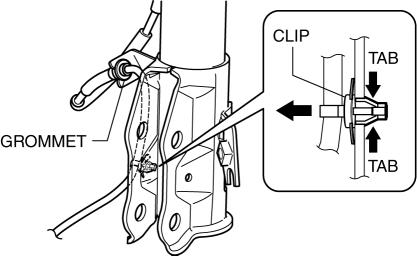
4. Remove the ABS wheel-speed sensor wiring harness grommet from the shock absorber.
5. Move the ABS wheel-speed sensor to a place out of the way.
6. Install the steering knuckle to the shock absorber, insert the bolts from the direction shown as follows, then tighten them to the specified torque.
- Vehicle left side: Insert the bolts from the vehicle rear.
- Vehicle right side: Insert the bolts from the vehicle front.
Joint Shaft Removal Note
1. Disconnect the drive shaft (RH) from the joint shaft using the SSTs.
2. Disconnect the joint shaft bracket from the cylinder block and remove the joint shaft.
CAUTION:
- The sharp edges of the joint shaft can slice or puncture the oil seal. Be careful when removing the joint shaft from the transaxle.
3. Install the SST to the transaxle after the joint shaft is removed.
Joint Shaft Clip Installation Note
1. Install a new clip onto the joint shaft with the opening facing upward.
CAUTION:
- Ensure that the diameter of the clip does not exceed the specification on installation.
2. After installation, measure the outer diameter.
- If it exceeds the specification, repeat Steps 1-2 using a new clip.

Outer diameter
- 31.2 mm {1.23 in}
Joint Shaft Installation Note
1. Temporary tighten the bolt A.
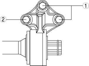
2. Tighten the bolt A with specified torque.
3. Tighten the bolt B with specified torque.
ABS Wheel-Speed Sensor Installation Note
1. Install the ABS wheel-speed sensor wiring harness grommet to the shock absorber as shown in the figure.
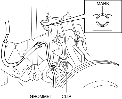
2. Install the ABS wheel-speed sensor wiring harness clip to the shock absorber.
3. Install the ABS wheel-speed sensor to the steering knuckle, then tighten the bolt (ABS wheel-speed sensor) to the specified torque.
4. Verify that the ABS wheel-speed sensor wiring harness is not twisted.
JOINT SHAFT DISASSEMBLY
1. Disassemble in the order indicated in the table.
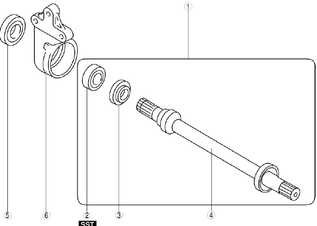
- Joint shaft component
- Bearing
- Dust seal (LH)
- Joint shaft
- Dust seal (RH)
- Bracket
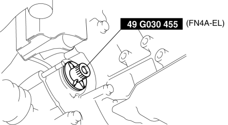
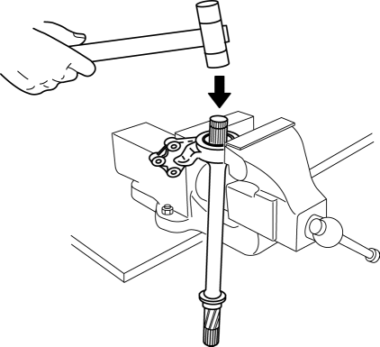
Joint Shaft Component Disassembly Note
1. Secure the bracket to the vise at the position shown in the figure and remove the joint shaft component using the plastic hammer.
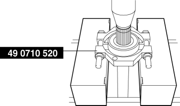
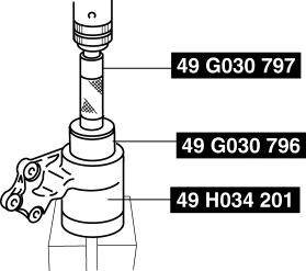
Bearing Disassembly Note
1. Remove the bearing from the joint shaft using the SST.
JOINT SHAFT ASSEMBLY
1. Assemble in the reverse order of disassembly.
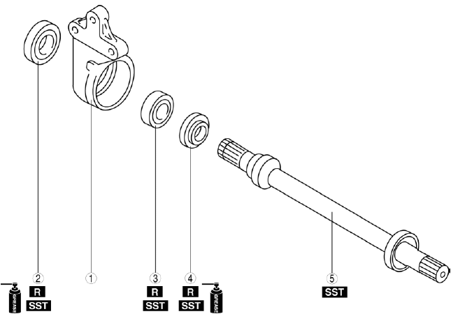
- Bracket
- Dust seal (RH)
- Bearing
- Dust seal (LH)
- Joint shaft
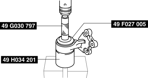
Dust Seal (RH) Assembly Note
1. Apply grease to a new dust seal lip.
2. Install the dust seal (RH) using the SSTs.
Bearing Assembly Note
1. Install a new bearing using the SSTs.
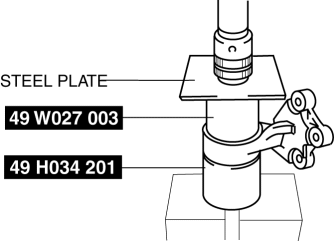
Dust Seal (LH) Assembly Note
1. Apply grease to a new dust seal lip.
2. Install a new dust seal (LH) using the SSTs and steel plate.
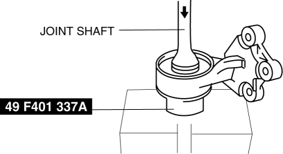
Joint Shaft Assembly Note
1. Press the joint shaft in using the SST and a press.
DRIVELINE/AXLE TECHNICAL DATA
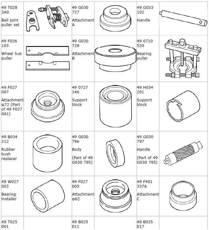
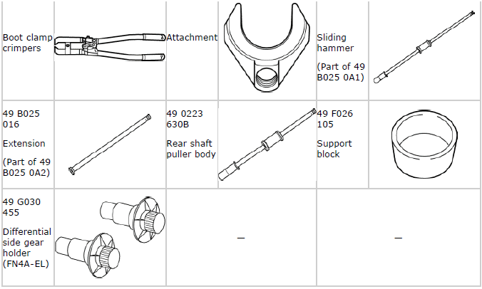
DRIVELINE/AXLE SST