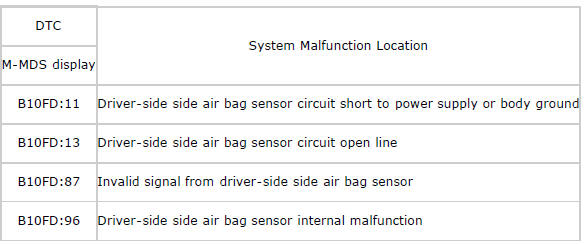
Mazda 2: DTC B10FD:11/B10FD:13/B10FD:87/B10FD:96
System Malfunction Location
Detection Condition
WARNING:
- Detection conditions are for understanding the DTC outline before performing an inspection. Performing an inspection according to only the detection conditions may cause injury due to an operating error, or damage the system. When performing an inspection, always follow the inspection procedure.
- Wiring harness between the driver-side side air bag sensor and SAS control module has a malfunction.
- Driver-side side air bag sensor has a malfunction.
Possible Causes
- Driver-side side air bag sensor connector malfunction
- Open or short circuit in the wiring harness between the driver-side side air bag sensor and SAS control module
- Driver-side side air bag sensor malfunction
- SAS control module malfunction
System Wiring Diagram
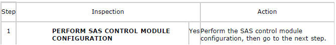
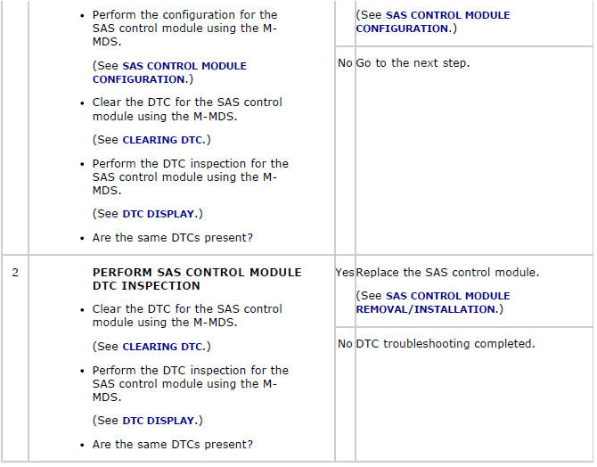
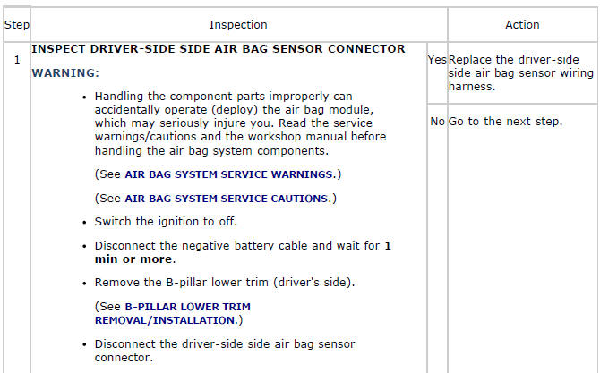
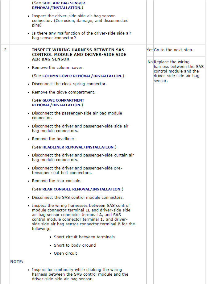
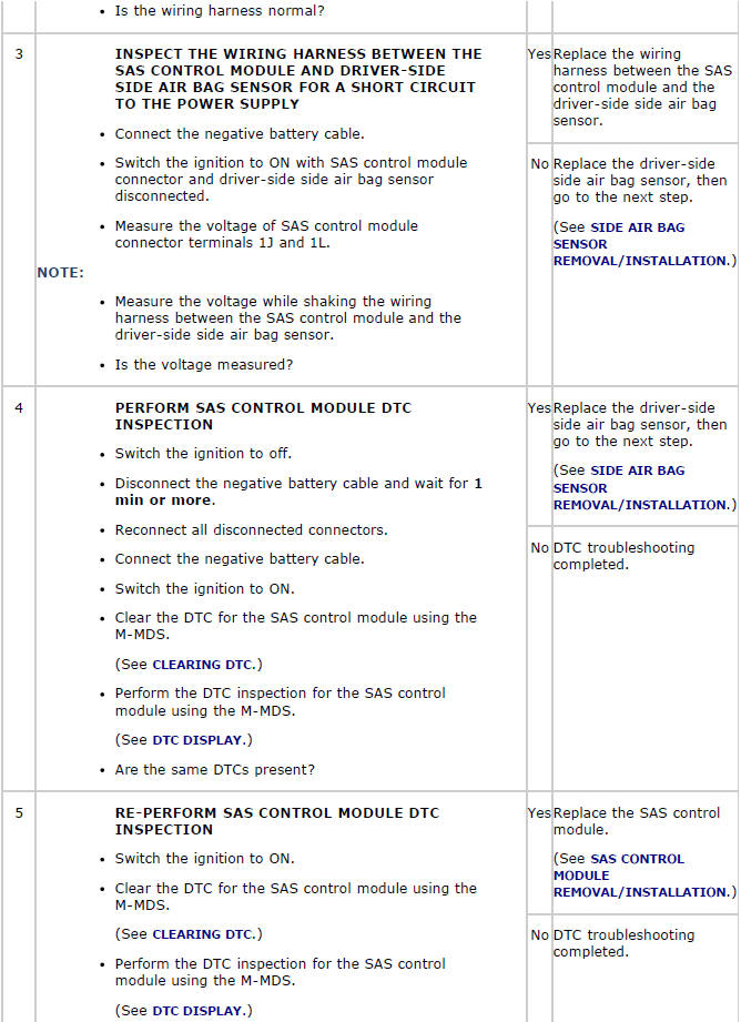
Diagnostic Procedure

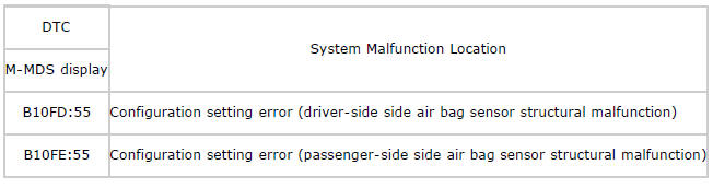
DTC B10FD:55/B10FE:55
System Malfunction Location
Detection Condition
WARNING:
- Detection conditions are for understanding the DTC outline before performing an inspection. Performing an inspection according to only the detection conditions may cause injury due to an operating error, or damage the system. When performing an inspection, always follow the inspection procedure.
- SAS control module configuration setting has not been done correctly
Possible Causes
- SAS control module configuration setting not implemented
- SAS control module configuration setting invalid
- SAS control module malfunction
Diagnostic Procedure