Mazda 2: DTC Table [Immobilizer System (Keyless Entry System) ]
NOTE:
- The security light flashes or illuminates under the following conditions
when the ignition
is switched to off or ACC.
- There is a malfunction:
- DTC 16 or below: Flashes for approx. 1 min and the DTC flash pattern indicated in the table below repeats 10 times.
- DTC 21 or higher: Illuminates for approx. 1 min and the DTC flash pattern indicated in the table below repeats 10 times.
- If more than one DTC is detected, only the DTC with the lowest number is displayed.
- There is no malfunction
- The security light illuminates for approx. 3 s and then turns off.
- There is a malfunction:
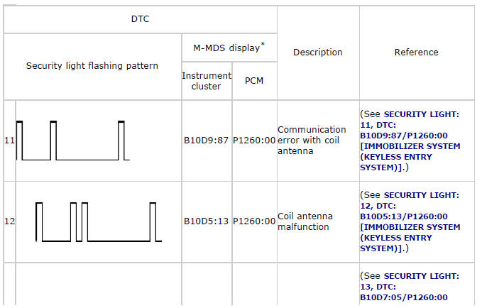
* The letters at the beginning of each DTC are only displayed when using the M-MDS, and refer to the following: B= Body system, P= Powertrain system, U= Network communication system
SECURITY LIGHT: 11, DTC: B10D9:87/P1260:00
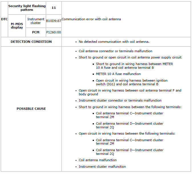
System Wiring Diagram
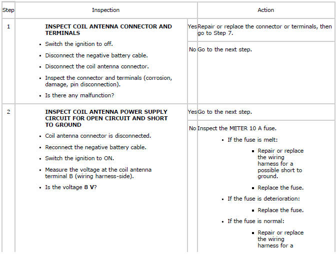
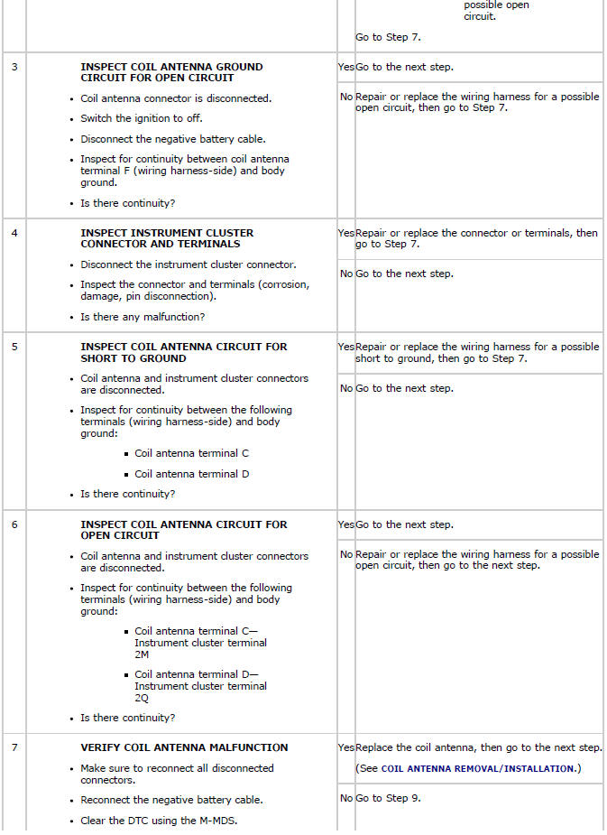
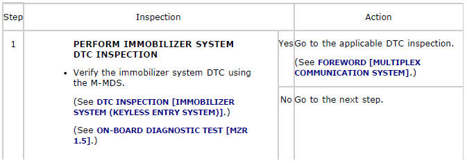
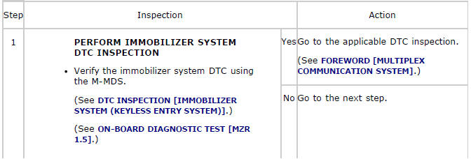
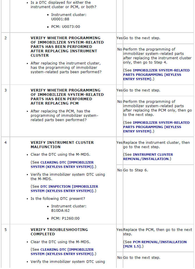
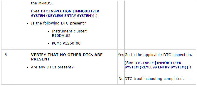
Diagnostic Procedure
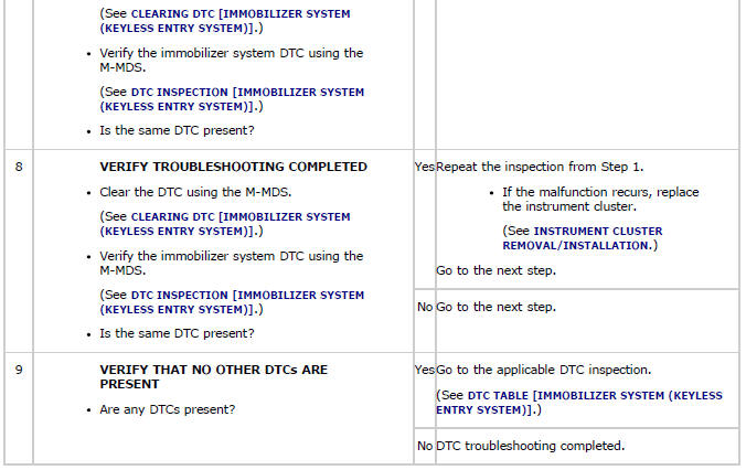
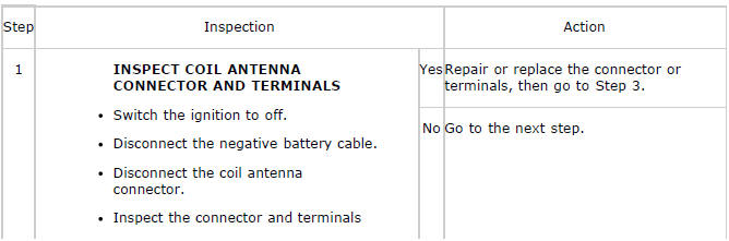
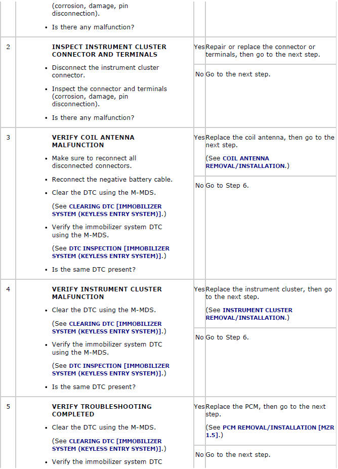
SECURITY LIGHT: 12, DTC: B10D5:13/P1260:00
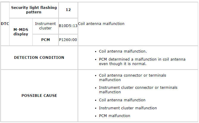
Diagnostic Procedure
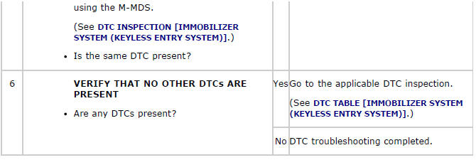
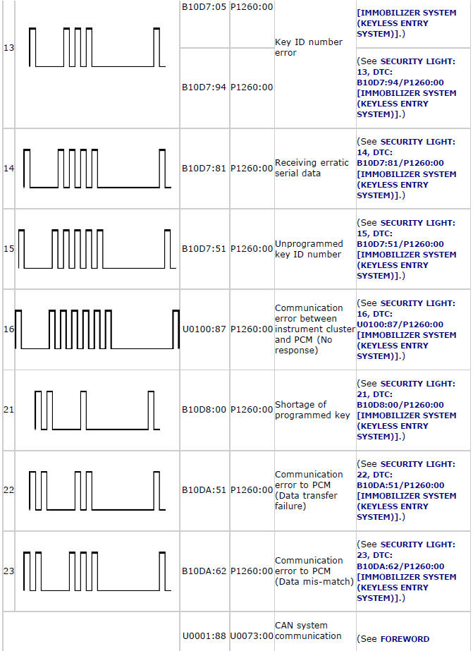
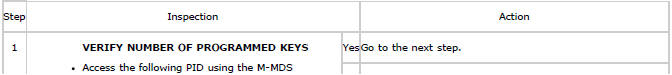
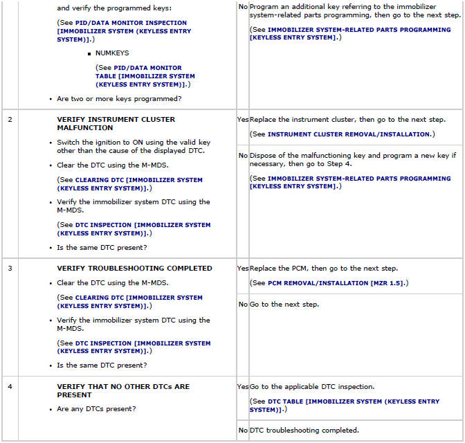
SECURITY LIGHT: 13, DTC: B10D7:05/P1260:00
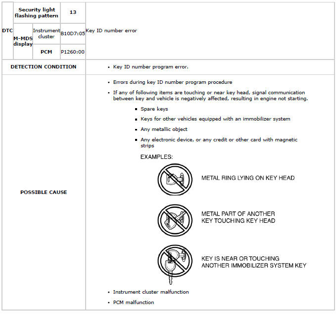
Diagnostic Procedure
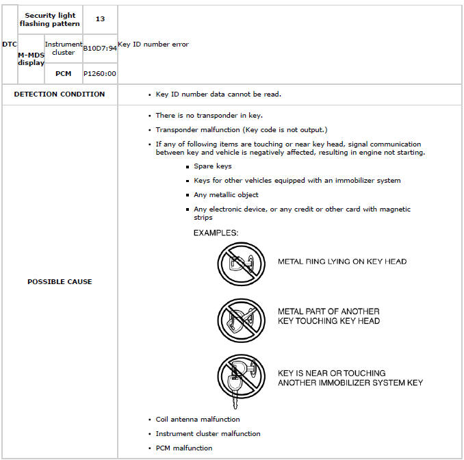
SECURITY LIGHT: 13, DTC: B10D7:94/P1260:00
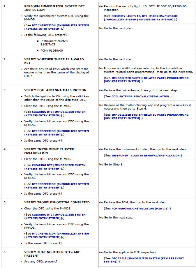
Diagnostic Procedure


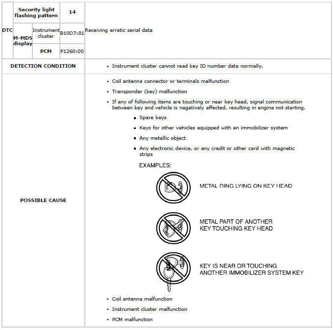
SECURITY LIGHT: 14, DTC: B10D7:81/P1260:00
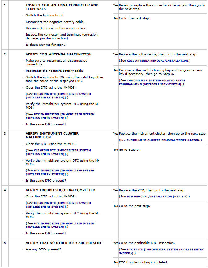
Diagnostic Procedure

SECURITY LIGHT: 15, DTC: B10D7:51/P1260:00
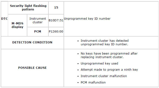
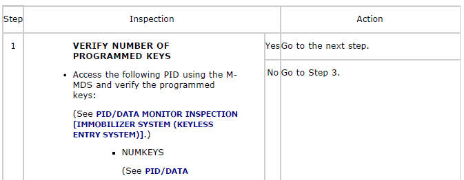
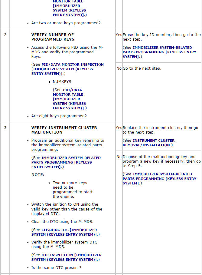
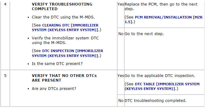
Diagnostic Procedure
SECURITY LIGHT: 16, DTC: U0100:87/P1260:00
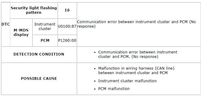
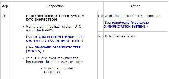
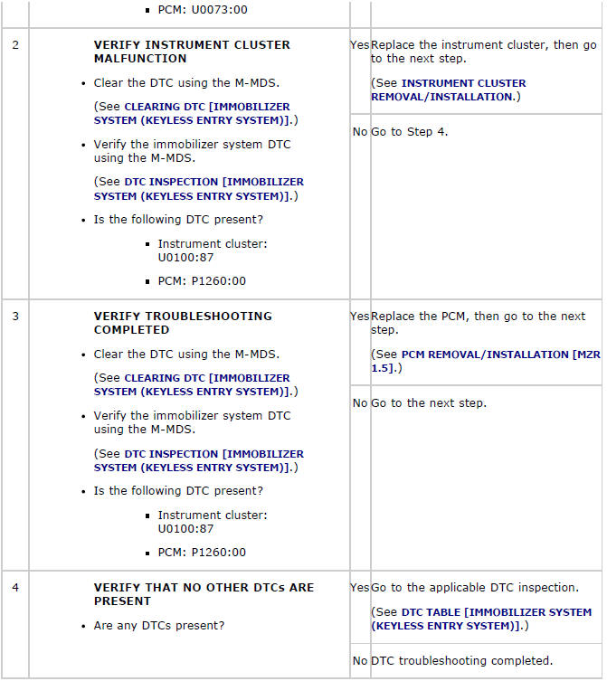
Diagnostic Procedure
SECURITY LIGHT: 21, DTC: B10D8:00/P1260:00
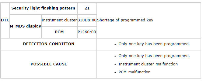
Diagnostic Procedure
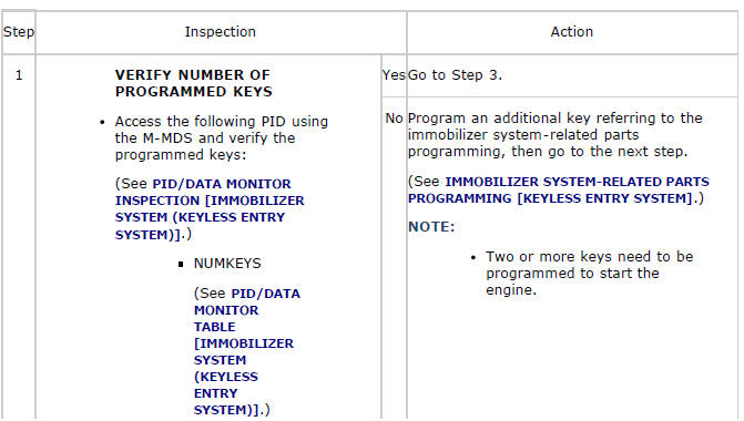
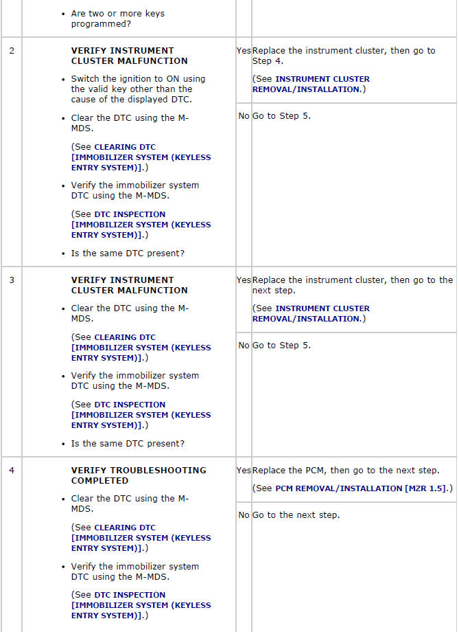
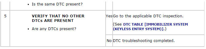
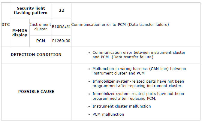
SECURITY LIGHT: 22, DTC: B10DA:51/P1260:00
Diagnostic Procedure
SECURITY LIGHT: 23, DTC: B10DA:62/P1260:00
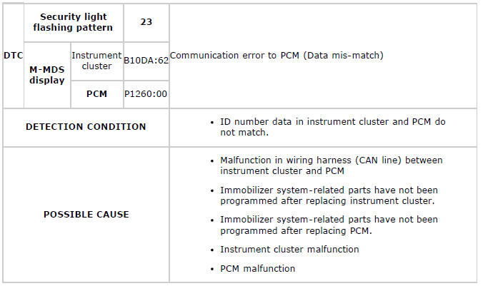
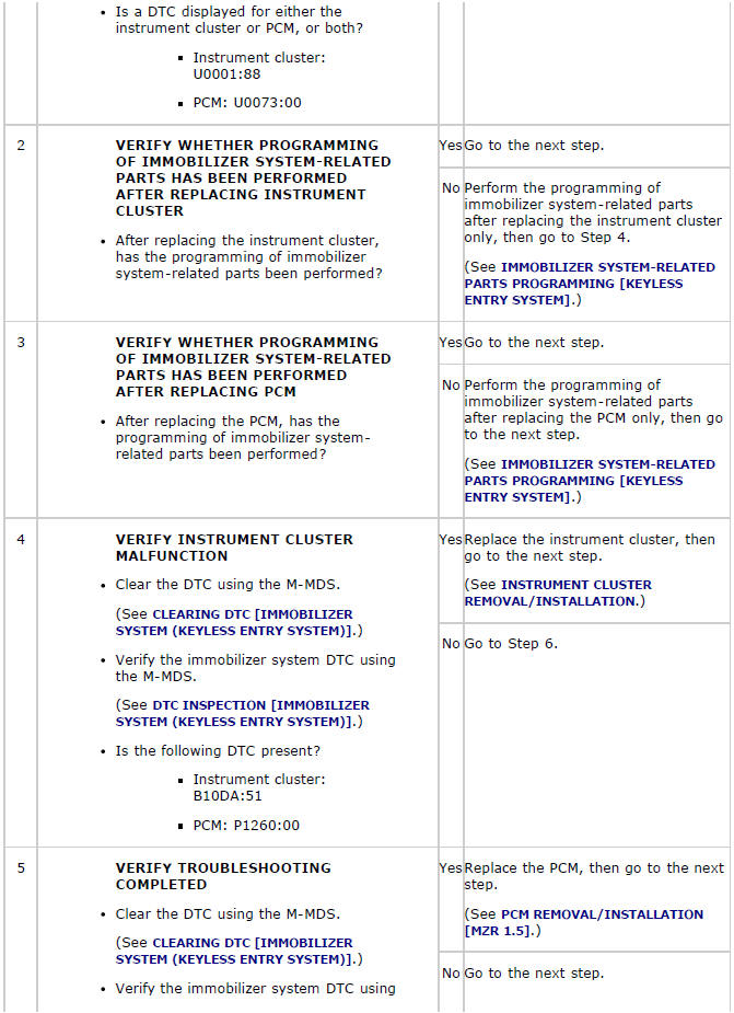
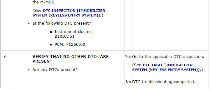
Diagnostic Procedure
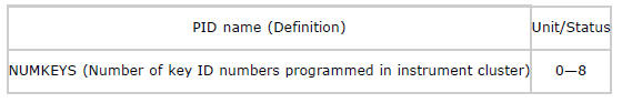
PID/DATA MONITOR INSPECTION [IMMOBILIZER SYSTEM (KEYLESS ENTRY SYSTEM) ]
1. Connect the M-MDS (IDS) to the DLC-2.
2. After the vehicle is identified, select the following items from the initialization screen of the IDS.
- Select "DataLogger".
- Select "Modules".
- Select "IC".
3. Select the applicable PID from the PID table.
4. Verify the PID data according to the directions on the screen.
NOTE:
- The PID data screen function is used for monitoring the calculated value of input/output signals in the module. Therefore, if the monitored value of the output parts is not within the specification, it is necessary to inspect the monitored value of input parts corresponding to the applicable output part control. In addition, because the system does not display an output part malfunction as an abnormality in the monitored value, it is necessary to inspect the output parts individually.
PID/DATA MONITOR TABLE [IMMOBILIZER SYSTEM (KEYLESS ENTRY SYSTEM) ]