Mazda 2: Keyless Receiver
KEYLESS RECEIVER REMOVAL/INSTALLATION [KEYLESS ENTRY SYSTEM]
1. Disconnect the negative battery cable.
2. Remove the glove compartment. (See GLOVE COMPARTMENT REMOVAL/INSTALLATION).
3. Remove in the order indicated in the table.
![Mazda 2. KEYLESS RECEIVER REMOVAL/INSTALLATION [KEYLESS ENTRY SYSTEM]](images/books/1059/mazda_2_keyless_receiver_3469.png)
- Connector
- Nut
- Keyless receiver
4. Install in the reverse order of removal.
KEYLESS RECEIVER INSPECTION [KEYLESS ENTRY SYSTEM]
1. Remove the glove compartment. (See GLOVE COMPARTMENT REMOVAL/INSTALLATION).
2. Measure the voltage according to the terminal voltage table.
- If the voltages cannot be verified as indicated in the terminal voltage
table,
inspect the parts under "Inspection item(s)".
- If the system does not work normally even though the parts or related wiring harnesses do not have any malfunction, replace the keyless receiver.
3. Disconnect the negative battery cable.
Terminal voltage table (reference)
![Mazda 2. KEYLESS RECEIVER INSPECTION [KEYLESS ENTRY SYSTEM]](images/books/1059/mazda_2_keyless_receiver_3470.png)
![Mazda 2. KEYLESS RECEIVER INSPECTION [KEYLESS ENTRY SYSTEM]](images/books/1059/mazda_2_keyless_receiver_3471.png)
![Mazda 2. KEYLESS RECEIVER INSPECTION [KEYLESS ENTRY SYSTEM]](images/books/1059/mazda_2_keyless_receiver_3472.png)
TRANSMITTER BATTERY REPLACEMENT [KEYLESS ENTRY SYSTEM]
1. Insert a flathead screwdriver into the transmitter notch and remove the key from the transmitter by pressing the tab.
![Mazda 2. TRANSMITTER BATTERY REPLACEMENT [KEYLESS ENTRY SYSTEM]](images/books/1059/mazda_2_keyless_receiver_3473.png)
2. Insert a flathead screwdriver into the transmitter notch and open the transmitter.
![Mazda 2. TRANSMITTER BATTERY REPLACEMENT [KEYLESS ENTRY SYSTEM]](images/books/1059/mazda_2_keyless_receiver_3474.png)
3. Remove the battery by pressing it in the direction of the arrow shown in the figure.
![Mazda 2. TRANSMITTER BATTERY REPLACEMENT [KEYLESS ENTRY SYSTEM]](images/books/1059/mazda_2_keyless_receiver_3475.png)
4. Install the new battery (CR1620) with the plus pole facing down.
![Mazda 2. TRANSMITTER BATTERY REPLACEMENT [KEYLESS ENTRY SYSTEM]](images/books/1059/mazda_2_keyless_receiver_3476.png)
5. Align the upper and lower covers and close the transmitter.
Battery type
- Lithium battery CR1620
Battery life
- Approx. 2 years (when used approx. 10 times/day)
6. Install the key to the transmitter.
NOTE:
- When connecting the key to the transmitter, grip the key and the transmitter as shown in the figure and connect until a click sound is heard.
- If the key is not completely connected to the transmitter, they may come apart.
![Mazda 2. TRANSMITTER BATTERY REPLACEMENT [KEYLESS ENTRY SYSTEM]](images/books/1059/mazda_2_keyless_receiver_3477.png)
TRANSMITTER ID CODE REGISTRATION [KEYLESS ENTRY SYSTEM]
NOTE:
- Verify that the other transmitter is not being operated around the servicing area while updating the ID code.
- After completing the work, remove the key from the steering lock and verify that all the door lock/unlock operation using the transmitter is correct.
![Mazda 2. TRANSMITTER ID CODE REGISTRATION [KEYLESS ENTRY SYSTEM]](images/books/1059/mazda_2_keyless_receiver_3478.png)
![Mazda 2. TRANSMITTER ID CODE REGISTRATION [KEYLESS ENTRY SYSTEM]](images/books/1059/mazda_2_keyless_receiver_3479.png)
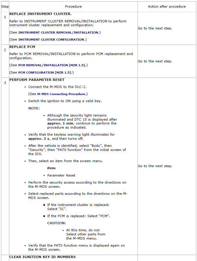
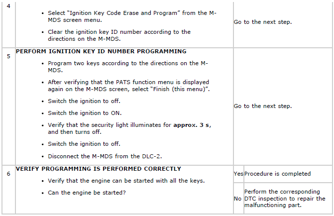
IMMOBILIZER SYSTEM-RELATED PARTS PROGRAMMING [KEYLESS ENTRY SYSTEM]
Foreword
- When replacing immobilizer system-related parts or programming an additional key, program the immobilizer system-related parts so that the system operates normally. For immobilizer system-related parts programming, Select programming procedures according to the service. (See Selection of Procedure for Immobilizer System-Related Parts Programming).
CAUTION:
- If any metallic or magnetic object is near the key, communication
between the key and the
vehicle may be obstructed, resulting in a failure to program the immobilizer
system-related parts.
Remove any metallic or magnetic objects, such as key holders, from the key when programming immobilizer system-related parts.
- If any of the following devices are inside the vehicle, programming of
immobilizer system-related
parts may fail. Do not bring any of the following devices or similar
products inside the vehicle
when programming immobilizer system-related parts.
- M-MDS
- Personal computer
- Devices that can send/receive radio waves
- If the engine is started during immobilizer system-related parts programming, the programming mode cancels. Therefore, do not start the engine unless indicated in the procedure. Repeat the procedure from the beginning if the engine is started during the immobilizer system-related parts programming.
NOTE:
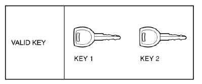
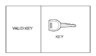
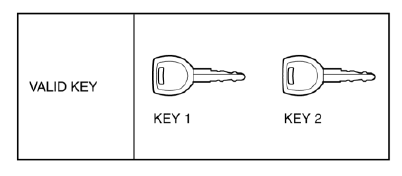
- The "Valid key" referred to in this manual indicates the key that can start the engine.
- Two or more key ID numbers must be programmed for the engine to start.
- A maximum of eight key ID numbers can be programmed for one vehicle.
- The number of programmed key ID numbers can be verified using the M-MDS.
- Do not select any screen menu other than the ones indicated in the procedure during M-MDS operation.
Selection of Procedure for Immobilizer System-Related Parts Programming
1. Verify that the room fuse is equipped.
2. Select applicable programming procedure from the service content of the immobilizer system-related parts.
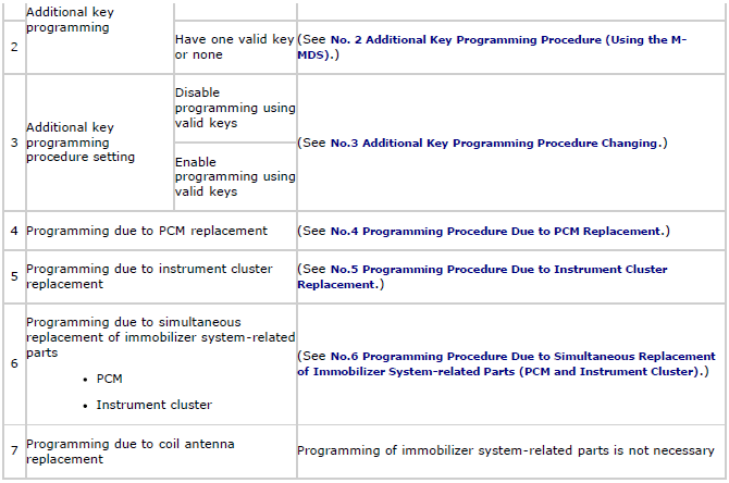
Immobilizer System-Related Parts Service and Programming Procedure Table
M-MDS Connecting Procedure
NOTE:
- Do not place the M-MDS in the vehicle while programming the immobilizer system.
1. Fully lower the door glass.
2. Connect the M-MDS to the DLC-2.
3. Place the M-MDS outside the vehicle.
CAUTION:
- Cover the vehicle body with a clean rag so as not to damage the vehicle body with the cable.
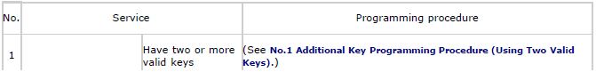
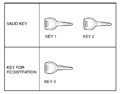
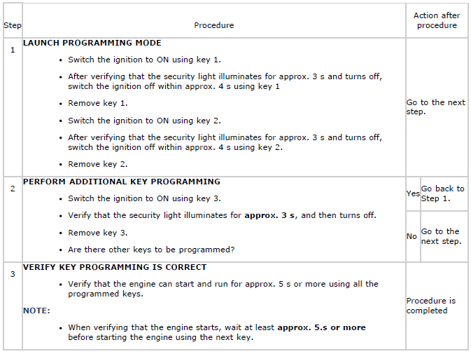
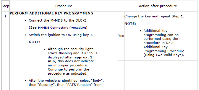
No.1 Additional Key Programming Procedure (Using Two Valid Keys)
Conditions
- Have two or more valid keys.
NOTE:
- If a key ID number cannot be programmed and DTC 15 is displayed, the maximum number of programmed keys may have been reached. Verify the number of programmed keys using the M-MDS.
- If eight keys have already been programmed and it is necessary to program other keys, the previously programmed key ID numbers must first be cleared.
- If "Customer spare key programming disable" is selected, perform additional key programming using the M-MDS. (See No. 2 Additional Key Programming Procedure (Using the M-MDS)).
Procedure
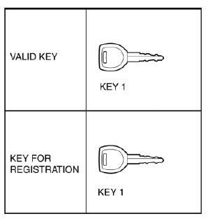
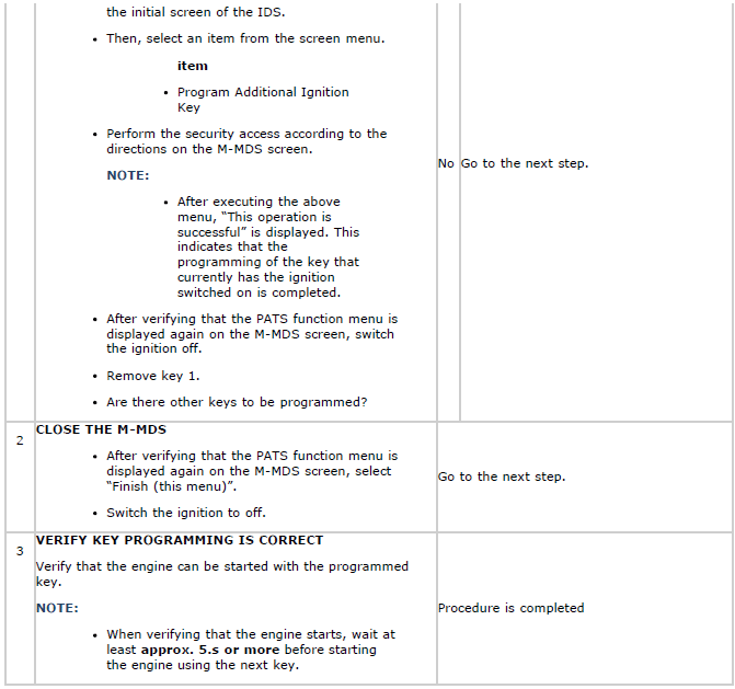
No. 2 Additional Key Programming Procedure (Using the M-MDS)
Conditions
- There is only one valid key, or none.
NOTE:
- If a key ID number cannot be programmed and DTC 15 is displayed, the maximum number of programmed keys may have been reached. Verify the number of programmed keys using the M-MDS.
- If eight keys have already been programmed and it is necessary to program other keys, the previously programmed key ID numbers must first be cleared.
Procedure
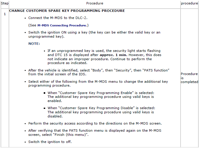
No.3 Additional Key Programming Procedure Changing
NOTE:
- This procedure is performed for disabling the No.1 Additional Key Programming Procedure (Using Two Valid Keys).
- The setting is "Customer spare key programming enable" when the vehicle is new or the keyless control module is replaced with a new one.
Procedure

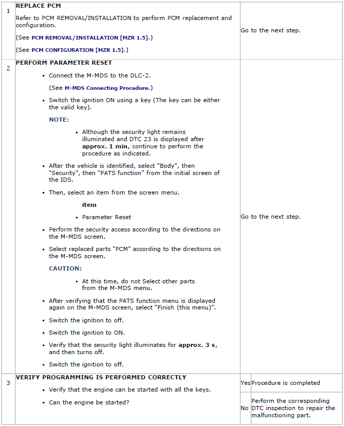
No.4 Programming Procedure Due to PCM Replacement
Conditions
- Have two or more valid keys.
Procedure

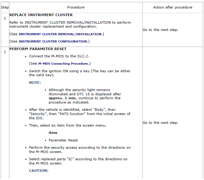
No.5 Programming Procedure Due to Instrument Cluster Replacement
NOTE:
- Since two or more keys need to be programmed to start the engine, program two or more keys after the replacement.
Conditions
- Have two or more keys to be programmed after the replacement.
Procedure
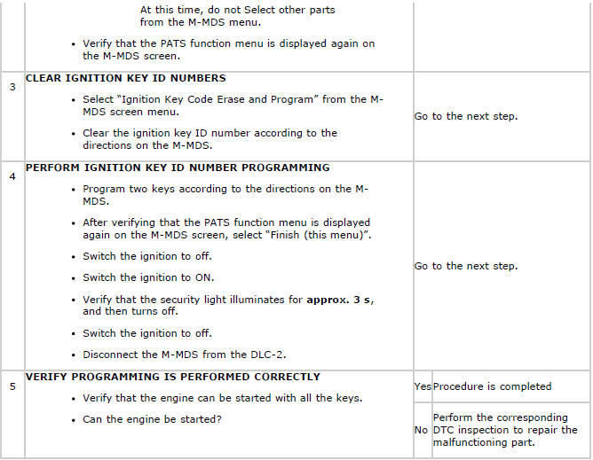
No.6 Programming Procedure Due to Simultaneous Replacement of Immobilizer System-related Parts (PCM and Instrument Cluster)
NOTE:
- Since two or more keys need to be programmed to start the engine, program two or more keys after the replacement.
Conditions
- Have two or more keys to be programmed after the replacement.
Procedure