Mazda 2: Malfunctioning Wheel Unit Identification
NOTE:
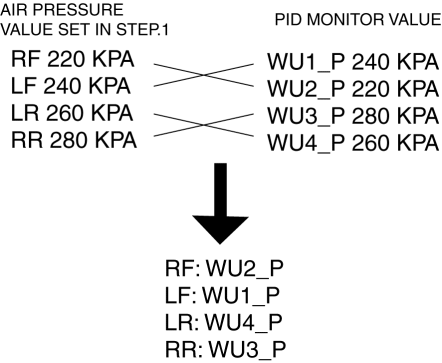
- The tire pressure monitoring system (TPMS) does not identify the location of the malfunctioning wheel unit on the vehicle (RF, LF, LR, RR). The TPMS identifies each wheel unit as No.1, No.2, No.3 and No.4. In order to identify the location of the wheel unit, perform the following procedure.
1. Adjust the air pressure as follows:
- RF: 220 kPa {2.2 kgf/cm2, 32 psi}
- LF: 240 kPa {2.4 kgf/cm2, 35 psi}
- LR: 260 kPa {2.6 kgf/cm2, 38 psi}
- RR: 280 kPa {2.8 kgf/cm2, 40 psi}
2. Switch the ignition to off.
3. Connect the M-MDS to the DLC-2.
4. Switch the ignition to ON.
5. Drive the vehicle at a speed of 25 km/h {15.5 mph} or more for 2 min or more.
6. Select the following PIDs using the M-MDS, and monitor them.
- WU1_P
- WU2_P
- WU3_P
- WU4_P
7. Determine which wheel unit identification code matches which wheel and tire by comparing the PID monitor values with the air pressure values set in Step 1.
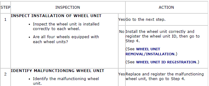
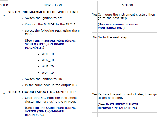
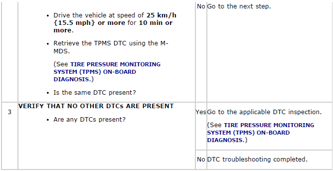
DTC C0077:00
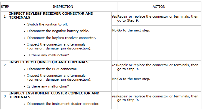
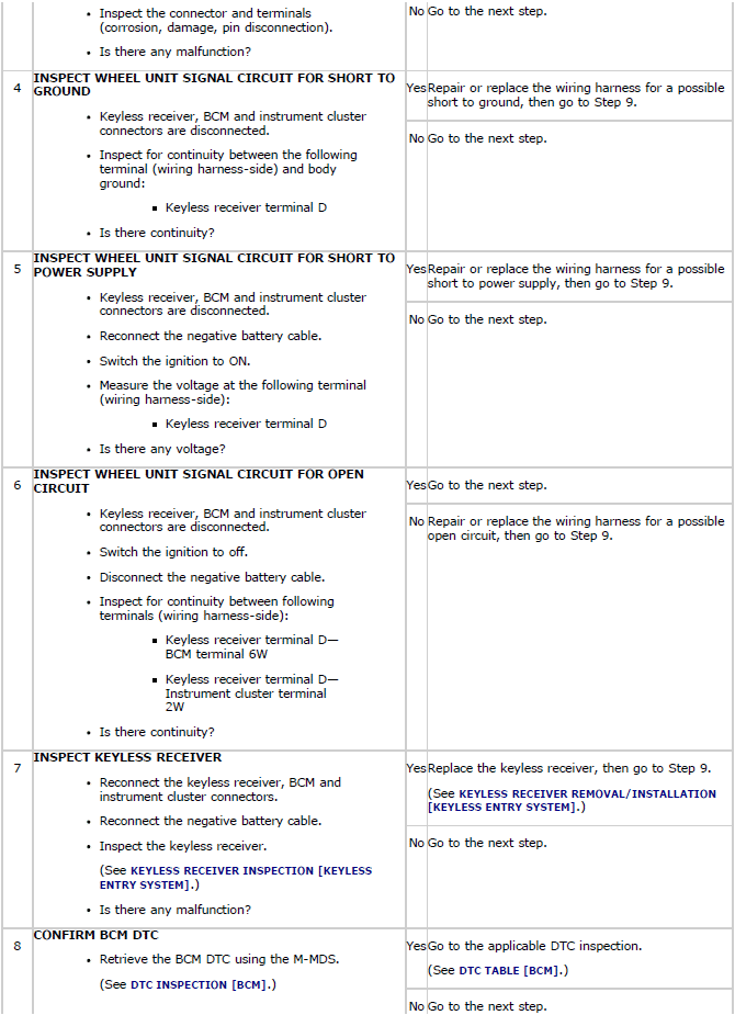
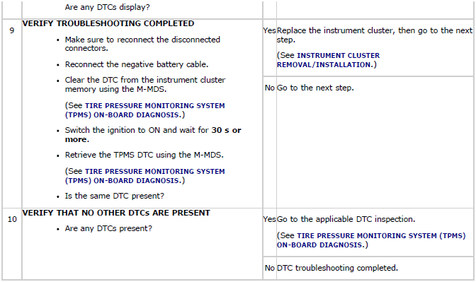
Diagnostic procedure
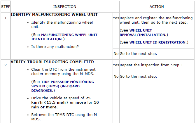
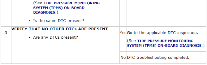
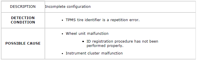
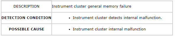
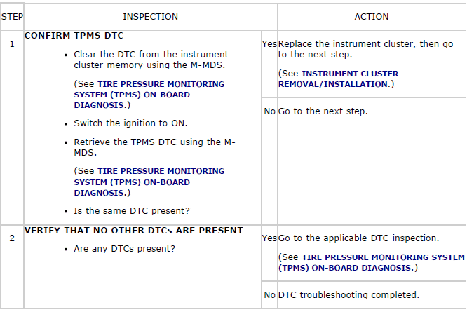
DTC C2011:49/C2012:49/C2013:49/C2014:49
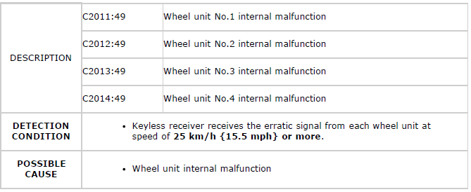
Diagnostic procedure
DTC C2011:87/C2012:87/C2013:87/C2014:87
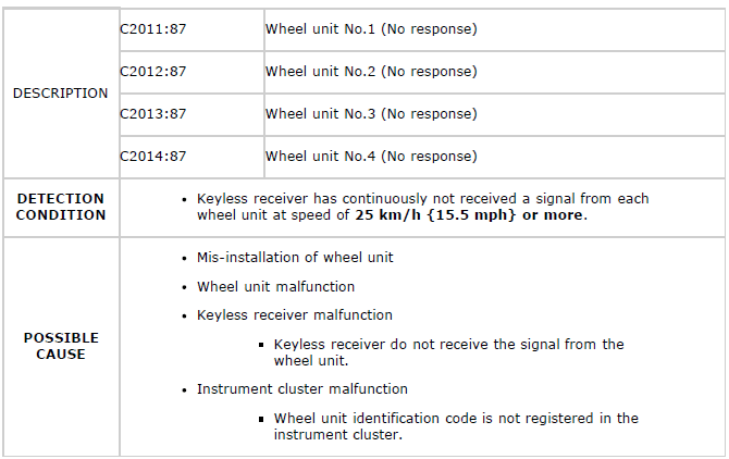
Diagnostic procedure
NOTE:
- If the wheel unit has been newly replaced, the TPMS warning light may
flashes before
the ID registration is complete, and DTC C2011:87, C2012:87, C2013:87 and
C2014:87
may be stored in the memory. In this case, reimplement the wheel unit ID
registration,
and after confirming that the TPMS warning light is no longer flashing,
erase the DTC.
If the TPMS warning light does not go out, a malfunction on any one of the wheel units may have occurred and the ID registration will not have been correctly performed.
Repeat the diagnostic procedure from Step 1 and perform and inspection.
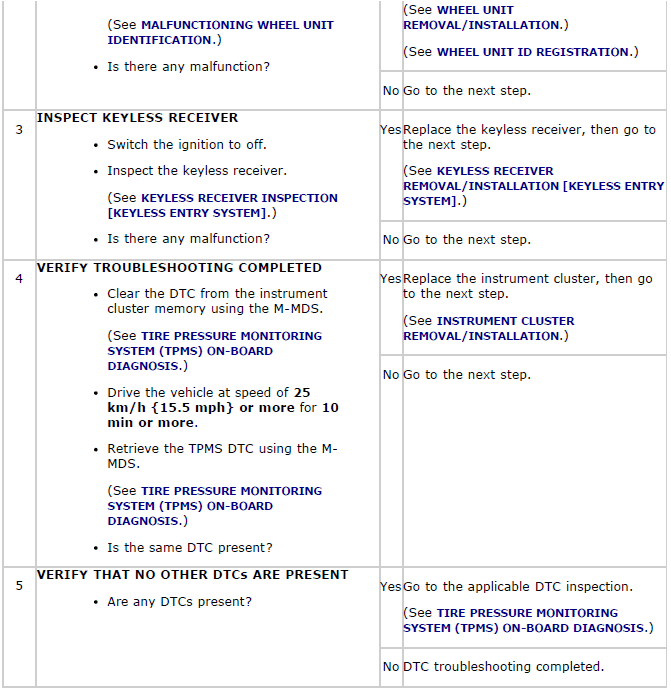
DTC U0127:00
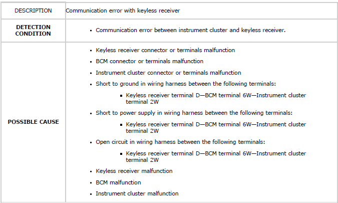
Diagnostic procedure
DTC U0300:00
Diagnostic procedure
DTC U3000:42
Diagnostic procedure
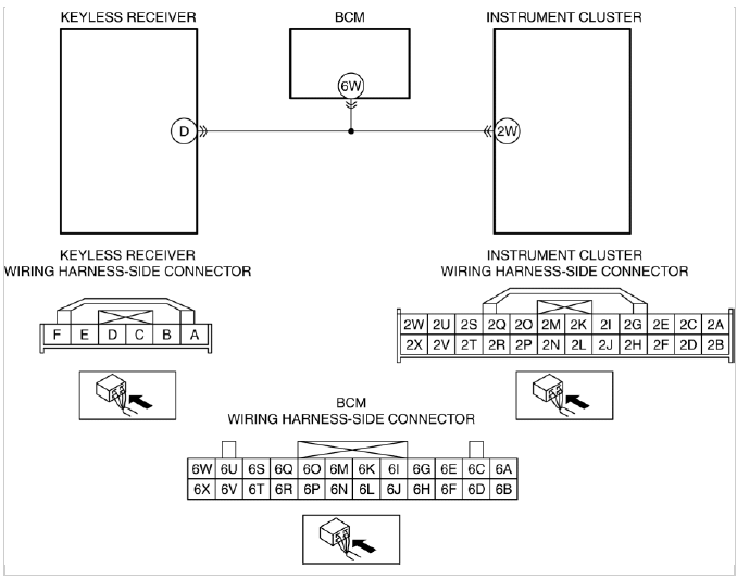
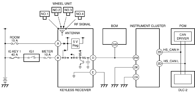
SYSTEM WIRING DIAGRAM
FOREWORD
- Before performing the steps in Symptom Troubleshooting, perform the On-board Diagnostic Inspection. To check the DTC, follow the DTC Inspection steps. (See TIRE PRESSURE MONITORING SYSTEM (TPMS) ON-BOARD DIAGNOSIS).

