Mazda 2: Transaxle Range (TR) Switch
TRANSAXLE RANGE (TR) SWITCH INSPECTION
CAUTION:
- Water or foreign objects entering the connector can cause a poor connection or corrosion. Be sure not to drop water or foreign objects on the connector when disconnecting it.
Operating Inspection
1. Perform the following procedures to inspect the TR switch.
- If there is any malfunction, adjust the TR switch. (See TRANSAXLE RANGE (TR) SWITCH ADJUSTMENT).
- Verify that the starter operates only when the ignition is switched to START with the selector lever in the P or N position.
- Verify that the back-up lights illuminate when selected to the R position with the ignition at ON.
- Verify that the positions of the selector lever and the selector indicator light are aligned.
On-Vehicle Inspection
1. Engage the parking brake and use wheel chocks at the front and rear of the wheels.
2. Disconnect the TR switch connector.
- Disconnect the negative battery cable.
- Disconnect the TR switch connector.
3. Inspect continuity as indicated in the table.

- If there is any malfunction, adjust the TR switch. (See TRANSAXLE RANGE (TR) SWITCH ADJUSTMENT).
- If a malfunction occurs after performing adjustments, replace the TR
switch.
(See TRANSAXLE RANGE (TR) SWITCH REMOVAL/INSTALLATION).
TRANSAXLE RANGE (TR) SWITCH ADJUSTMENT
CAUTION:
- Water or foreign objects entering the connector can cause a poor connection or corrosion. Be sure not to drop water or foreign objects on the connector when disconnecting it.
1. Engage the parking brake and use wheel chocks at the front and rear of the wheels.
2. Shift the selector lever to the N position.
3. Disconnect the TR switch connector.
- Disconnect the negative battery cable.
- Disconnect the TR switch connector.

4. Loosen the TR switch.
- Remove the clip from the selector cable.
- Disconnect the selector cable from manual shaft lever.
- Loosen the TR switch installation bolts.
5. Adjust the TR switch.
- Verify that the manual shaft is aligned with the N position.
- Adjust the TR switch between terminals B and C until the resistance becomes specification.
TR switch specification
- 713-787 ohms
- Tighten the TR switch installation bolts.
Tightening torque
- 8-11 N*m {82-112 kgf*cm, 71-97 in*lbf}
TRANSAXLE RANGE (TR) SWITCH REMOVAL/INSTALLATION
CAUTION:
- Water or foreign objects entering the connector can cause a poor connection or corrosion. Be sure not to drop water or foreign objects on the connector when disconnecting it.
1. Engage the parking brake and use wheel chocks at the front and rear of the wheels.
2. Shift the selector lever to the N position.
3. Disconnect the negative battery cable.
4. Remove in the order indicated in the table.
5. Install in the reverse order of removal.
6. Inspect the TR switch. (See TRANSAXLE RANGE (TR) SWITCH INSPECTION).
- Connector
- Clip
- Selector cable
- Manual shaft nut
- Washer
- Manual shaft lever
- TR switch
Manual Shaft Nut Removal Note
1. Set the adjustable wrench as shown to hold the manual shaft lever and loosen the manual shaft nut.
CAUTION:
- Do not use an impact wrench. Hold the manual shaft lever when removing the manual shaft nut, or the transaxle may be damaged.
- Do not apply torque to the manual shaft as bending or breakage of the spring pin installed to the manual shaft could damage the TR switch and cause a selector lever malfunction.
TR switch Installation Note
1. Verify that the manual shaft is aligned with the N position.
2. Adjust the TR switch between terminals B and C until the resistance becomes specification.

TR switch specification
- 713-787 ohms
3. Tighten the TR switch installation bolts.
Tightening torque
- 8-11 N*m {82-112 kgf*cm, 71-97 in*lbf}
Manual Shaft Nut Installation Note
1. Set the adjustable wrench as shown to hold the manual shaft lever and tighten the manual shaft nut.
CAUTION:
- Do not use an impact wrench. Hold the manual shaft lever when installing the manual shaft nut, or the transaxle may be damaged
- Do not apply torque to the manual shaft as bending or breakage of the spring pin installed to the manual shaft could damage the TR switch and cause a selector lever malfunction.
Tightening torque
- 32-46 N*m {3.3-4.6 kgf*m, 24-33 ft*lbf}
O/D OFF SWITCH INSPECTION
CAUTION:
- Water or foreign objects entering the connector can cause a poor connection or corrosion. Be sure not to drop water or foreign objects on the connector when disconnecting it.
1. Disconnect the selector lever component connector.
- Disconnect the negative battery cable.
- Remove the side wall. (See SIDE WALL REMOVAL/INSTALLATION).
- Remove the front console component. (See FRONT CONSOLE COMPONENT REMOVAL/INSTALLATION).
- Disconnect the selector lever component connector.
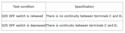
2. Verify continuity as indicated in the table.
- If there is any malfunction, replace the selector lever component. (See AUTOMATIC TRANSAXLE SHIFT MECHANISM REMOVAL/INSTALLATION).
O/D OFF switch specification
O/D OFF SWITCH REMOVAL/INSTALLATION
NOTE:
- The O/D OFF switch is built into the selector lever component.
1. If the O/D OFF switch is replaced, replace the selector lever component. (See AUTOMATIC TRANSAXLE SHIFT MECHANISM REMOVAL/INSTALLATION).

