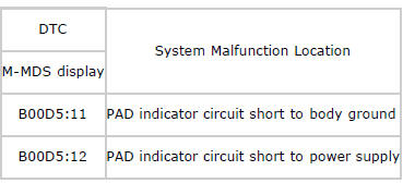
Mazda 2: DTC B00D5:11/B00D5:12
System Malfunction Location
Detection Condition
WARNING:
- Detection conditions are for understanding the DTC outline before performing an inspection. Performing an inspection according to only the detection conditions may cause injury due to an operating error, or damage the system. When performing an inspection, always follow the inspection procedure.
- Malfunction in PAD indicator circuit
Possible Causes
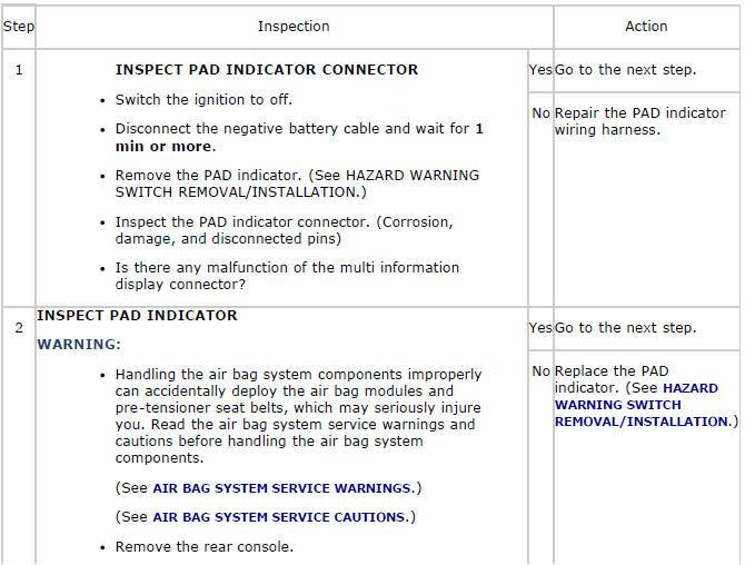
- PAD indicator connector malfunction
- PAD indicator malfunction
- Open or short circuit or short to ground or short to power supply in wiring harness between PAD indicator and SAS control module
- SAS control module malfunction
System Wiring Diagram
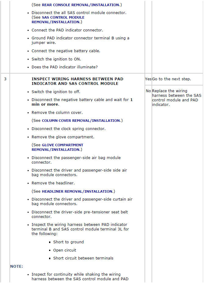
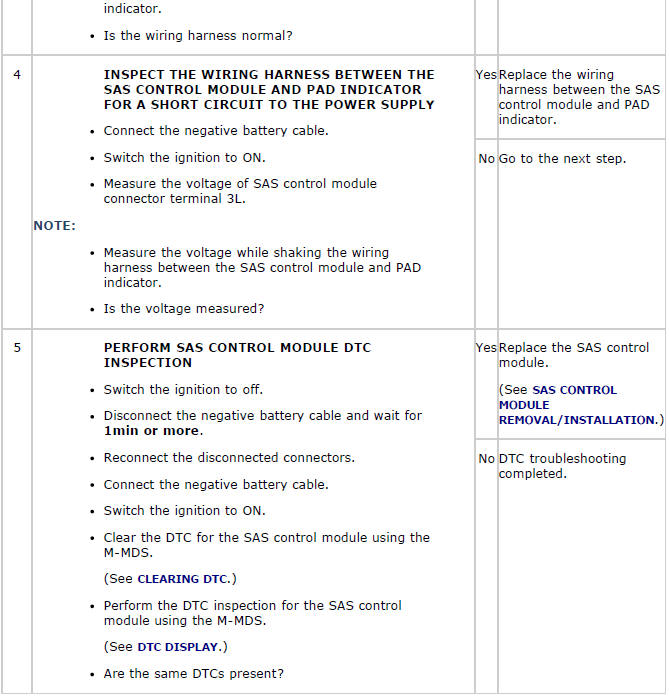
Diagnostic Procedure
DTC B00D5:55
System Malfunction Location
- Configuration setting error
Detection Condition
WARNING:
- Detection conditions are for understanding the DTC outline before performing an inspection. Performing an inspection according to only the detection conditions may cause injury due to an operating error, or damage the system. When performing an inspection, always follow the inspection procedure.
- SAS control module configuration setting has not been done correctly
Possible Causes
- SAS control module configuration setting not implemented
- SAS control module configuration setting invalid
- PAD indicator accidentally assembled to vehicle not equipped with seat weight sensor SAS control module malfunction
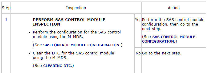
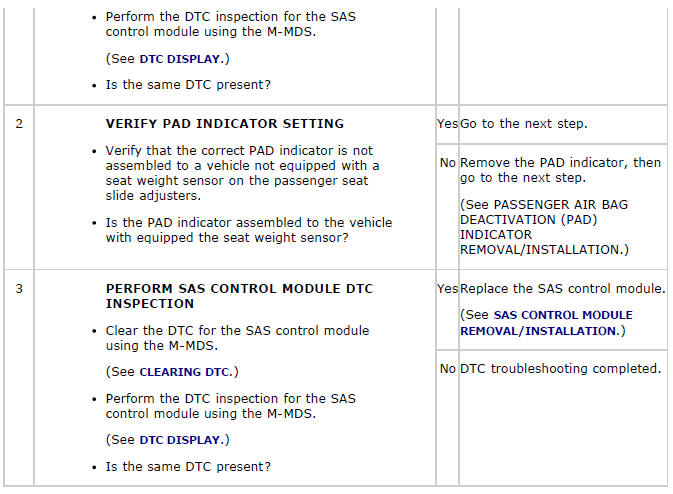
Diagnostic Procedure
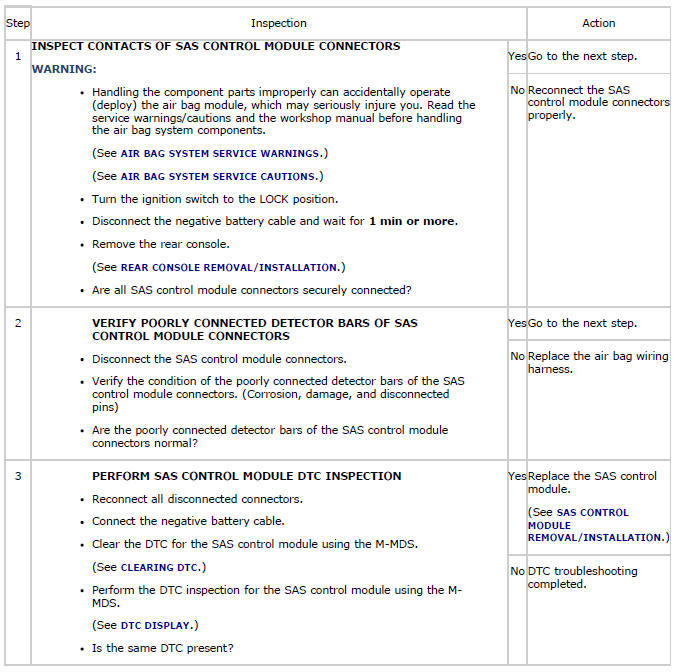
DTC B1011:95
System Malfunction Location
- SAS control module connectors are poorly connected
Detection Condition
WARNING:
- Detection conditions are for understanding the DTC outline before performing an inspection. Performing an inspection according to only the detection conditions may cause injury due to an operating error, or damage the system. When performing an inspection, always follow the inspection procedure.
- No continuity between poorly connected detector bar terminals of the SAS control module
Possible Causes
- SAS control module connectors are poorly connected
- SAS control module connector malfunction
- SAS control module malfunction
System Wiring Diagram
Diagnostic Procedure