Mazda 2: Front Door Latch and Lock Actuator
FRONT DOOR LATCH AND LOCK ACTUATOR REMOVAL/INSTALLATION
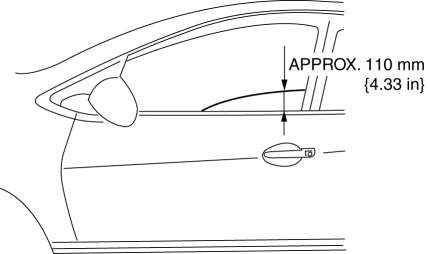
1. To access the glass installation bolt, position the front door glass so that the distance from the top of the front door glass to the upper part of the front beltline molding is approx. 110 mm {4.33 in}.

2. Disconnect the negative battery cable.
3. Remove the following parts:
- Inner garnish (See INNER GARNISH REMOVAL/INSTALLATION).
- Front door trim (See FRONT DOOR TRIM REMOVAL/INSTALLATION).
- Front inner handle (See DOOR LOCK-LINK SWITCH INSPECTION).
- Front door speaker (See FRONT DOOR SPEAKER REMOVAL/INSTALLATION).
- Front door glass (See FRONT DOOR GLASS REMOVAL/INSTALLATION).
- Front door module panel (See FRONT DOOR MODULE PANEL REMOVAL/INSTALLATION).
- Rod protector (See FRONT DOOR KEY CYLINDER REMOVAL/INSTALLATION).
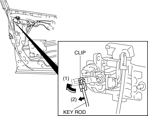
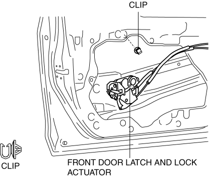
4. Lift the clip in the direction of the arrow (1), and pull out the key rod in the direction of the arrow (2).
5. Remove the screw
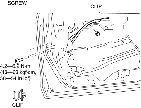
6. Detach the clips.
7. Press down the rod holder of the front door latch and lock actuator in the direction of the arrow.
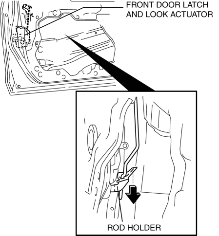
8. Maintaining the condition in procedure 7, remove the front door latch and lock actuator.
9. Install in the reverse order of removal.
FRONT DOOR LATCH AND LOCK ACTUATOR INSPECTION
1. The following actuators and switches are integrated with the front door latch and lock actuator. Inspect the front door latch and lock actuator according to each inspection procedure for the following items.
- Front door lock actuator (See FRONT DOOR LOCK ACTUATOR INSPECTION).
- Door lock-link switch (See DOOR LOCK-LINK SWITCH INSPECTION).
- Door latch switch (See FRONT DOOR LATCH SWITCH INSPECTION).
- Front door key cylinder (See FRONT DOOR KEY CYLINDER SWITCH INSPECTION).
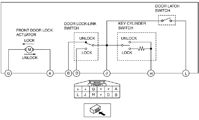
LH
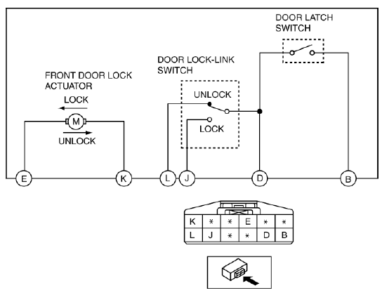
RH
FRONT DOOR LOCK ACTUATOR INSPECTION
1. To access the glass installation bolt, position the front door glass so that the distance from the top of the front door glass to the upper part of the front beltline molding is approx. 110 mm {4.33 in}.
2. Disconnect the negative battery cable.
3. Remove the following parts:
- Inner garnish (See INNER GARNISH REMOVAL/INSTALLATION).
- Front door trim (See FRONT DOOR TRIM REMOVAL/INSTALLATION).
- Front door speaker (See FRONT DOOR SPEAKER REMOVAL/INSTALLATION).
- Front door glass (See FRONT DOOR GLASS REMOVAL/INSTALLATION).
- Front door module panel (See FRONT DOOR MODULE PANEL REMOVAL/INSTALLATION).
- Front door latch and lock actuator (See FRONT DOOR LATCH AND LOCK ACTUATOR REMOVAL/INSTALLATION).
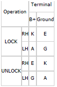
4. Apply battery positive voltage and connect the ground to each terminal, and then verify the operation.
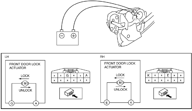
- If not as indicated in the table, replace the front door latch and lock actuator.