Mazda 2: Lighting Systems
LIGHTING SYSTEMS LOCATION INDEX
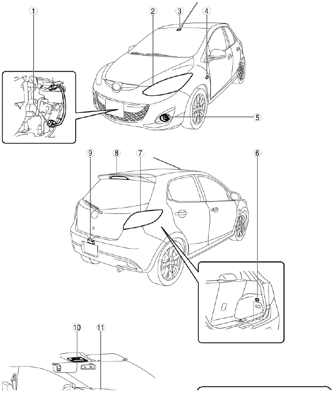
- Back-up light switch
- Front combination light
- Auto light sensor
- Side turn light
- Front fog light
- Cargo compartment light
- Rear combination light
- High-mount brake light
- License plate light
- Interior light
- Hazard warning switch
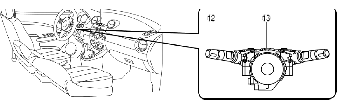
- Light switch
- Combination switch
FRONT COMBINATION LIGHT REMOVAL/INSTALLATION
1. Disconnect the negative battery cable.
2. Remove the front bumper. (See FRONT BUMPER REMOVAL/INSTALLATION).
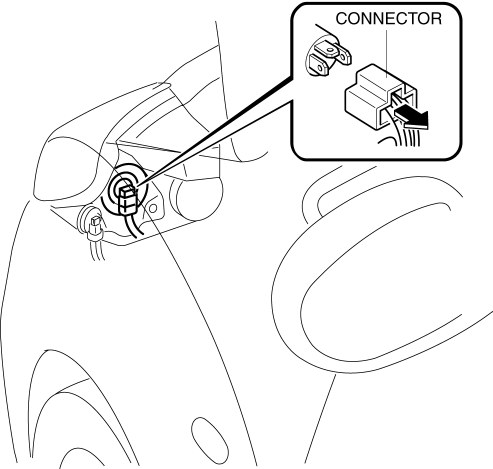
3. Disconnect the connector.
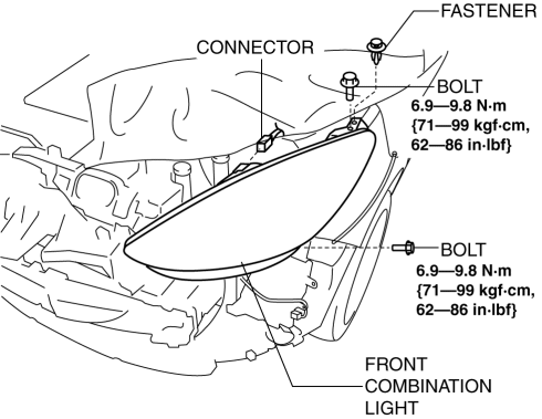
4. Remove the bolt.
5. Remove the fastener.
6. Remove the front combination light.
7. Install in the reverse order of removal.
8. Adjust the headlight aiming. (See HEADLIGHT AIMING).
HEADLIGHT AIMING
NOTE:
- The reflectors for the low and high beams are integrated. Therefore, perform the headlight aiming adjustment on either the low or high beam.
Low-beam Adjustment
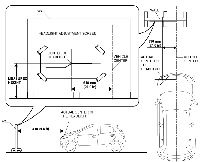
1. Point the headlight beams to a wall and verify that the headlight beams are as shown in the figure.
2. Make a headlight adjustment screen as shown in the figure using double-weight, white paper.
3. Adjust the tire pressure to the specification.
4. Park the vehicle on level ground, in an unloaded condition.
5. Sit on the driver-side seat alone.
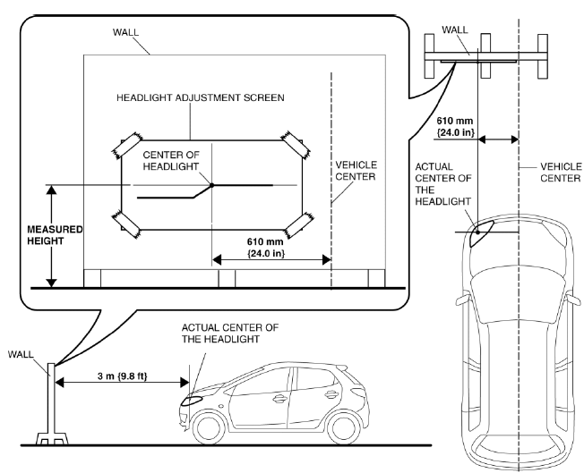
6. Put the white screen in front of the vehicle.
7. Line up the headlights with the white screen at a distance of 3 m {9.8 ft} apart.
8. Measure the height at the center of the headlight.
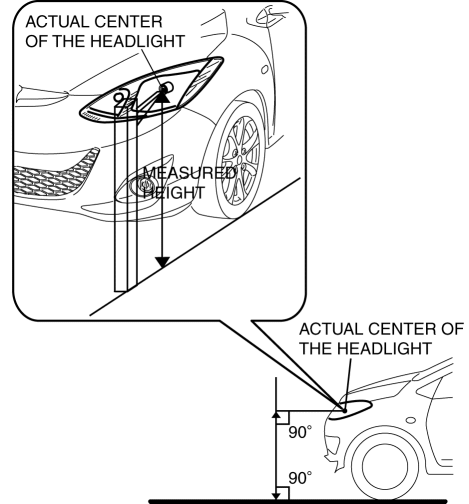
NOTE:
- Since the height of the vehicle varies depending on the vehicle situation, measure the height of the center of the headlight using the actual vehicle.
9. Align the center of the adjustment screen with the position indicated in the figure, then affix the screen to the wall.
10. Start the engine and charge the battery.
11. Turn on the headlight low beams.
12. Block the light of the headlight which is not adjusted.
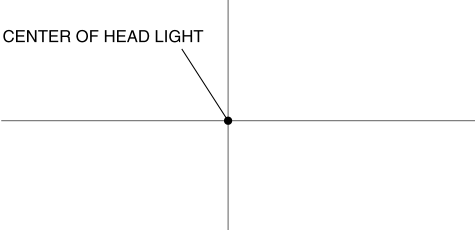
13. Verify that the elbow point of the headlight is at the position indicated by the adjustment screen.
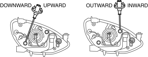
- If the elbow point is not at the position indicated by the adjustment screen, turn the adjustment screw as shown in the figure to adjust the elbow point to the position indicated by the adjustment screen.
High-beam Adjustment
1. Make a headlight adjustment screen as shown in the figure using double-weight, white paper.
2. Adjust the tire pressure to the specification.
3. Park the vehicle on level ground, in an unloaded condition.
4. Sit on the driver-side seat alone.
5. Put the wall in front of the vehicle.
6. Line up the headlights with the wall at a distance of 3 m {9.8 ft} apart.
7. Measure the height at the center of the headlight.

NOTE:
- Since the height of the vehicle varies depending on the vehicle situation, measure the height of the center of the headlight using the actual vehicle.
8. Align the center of the adjustment screen with the position indicated in the figure, then affix the screen to the wall.
9. Start the engine and charge the battery.
10. Turn on the headlight high beams.
11. Block the light of the headlight which is not adjusted using a partition.
12. Verify that the center of the hot zone (the bright part of high beam) is at the center of the headlight on the adjustment screen.
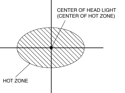
- If the center of the hot zone is not at the center of the headlight on the adjustment screen, turn the adjustment screw to adjust the center of the hot zone.

HEADLIGHT BULB REMOVAL/INSTALLATION
1. Disconnect the negative battery cable.
2. Remove the fasteners and slightly bend back the mudguard. (LH only) 3. Disconnect the connector.
4. Remove the rubber cover.
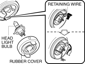
5. Press the bulb retaining wire in the direction of the arrow to release the lock.
6. Remove the headlight bulb.
CAUTION:
A bulb generates extremely high heat when it is illuminated. If the surface of the bulb is soiled, heat of higher temperature than normal will build, shortening the life of the bulb. When replacing the bulb, hold the metal flange, not the glass.
7. Install in the reverse order of removal.
PARKING LIGHT BULB REMOVAL/INSTALLATION
1. Disconnect the negative battery cable.
2. Rotate the socket in the direction of the arrow (1) and remove it.
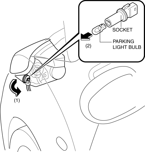
3. Remove the parking light bulb from the socket in the direction of the arrow (2).
4. Install in the reverse order of removal.
FRONT TURN LIGHT BULB REMOVAL/INSTALLATION
1. Disconnect the negative battery cable.
2. Rotate the socket in the direction of the arrow (1) and remove it.
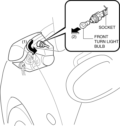
3. Remove the front turn light bulb from the socket in the direction of the arrow (2).
4. Install in the reverse order of removal.
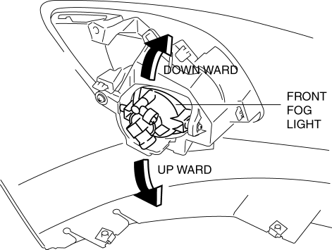
FRONT FOG LIGHT REMOVAL/INSTALLATION
1. Disconnect the negative battery cable.
2. Lift up the vehicle.
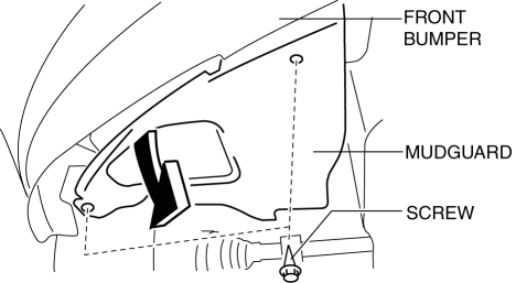
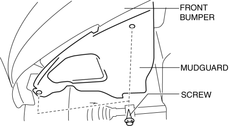
3. Remove the screw A shown in the figure and bend back the mudguard in the direction of the arrow.

4. Disconnect the connector.
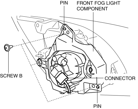
5. Remove the screw B.
6. Remove the front fog light component.
7. Remove the screw C.
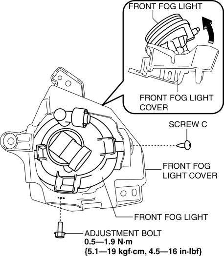
8. Remove the adjustment bolt.
9. Pull the front fog light in the direction of the arrow shown in the figure and remove it from the front fog light cover.
10. Install in the reverse order of removal.
11. Adjust the front fog light aiming. (See FRONT FOG LIGHT AIMING).
FRONT FOG LIGHT BULB REMOVAL/INSTALLATION
1. Disconnect the negative battery cable.
2. Remove the screws shown in the figure and bend back the mudguard in the direction of the arrow.

3. Disconnect the connector.
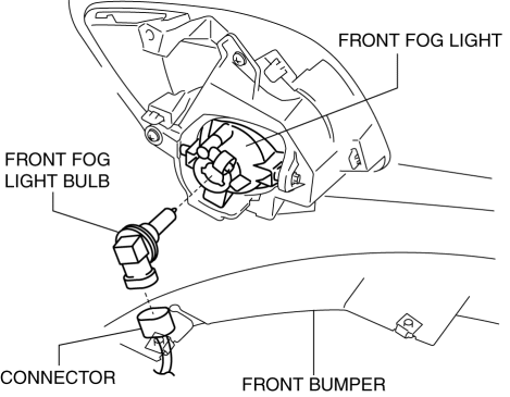
4. Remove the front fog light bulb.
CAUTION:
- A bulb generates extremely high heat when it is illuminated. If the surface of the bulb is soiled, heat of higher temperature than normal will build, shortening the life of the bulb. When replacing the bulb, hold the metal flange, not the glass.
5. Install in the reverse order of removal. (See Front Fog Light Bulb Installation Note).
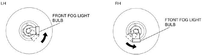
Front Fog Light Bulb Installation Note
1. Install the front fog light bulb by turning it in the direction of the arrow.
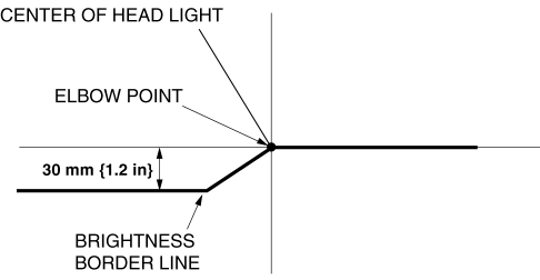
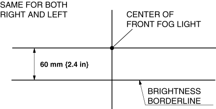
FRONT FOG LIGHT AIMING
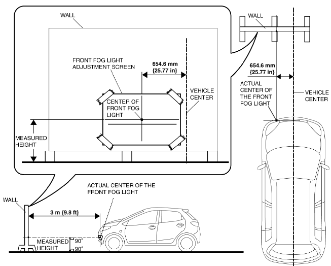
1. Make a front fog light adjustment screen as shown in the figure using double-weight, white paper.
2. Adjust the tire pressure to the specification.
3. Position the unloaded vehicle on a flat, level surface.
4. Seat one person in the driver's seat.
5. Line up the front fog lights with the white screen at a distance of 3 m {9.8 ft} apart.
6. Measure the height at the center of the front fog light.
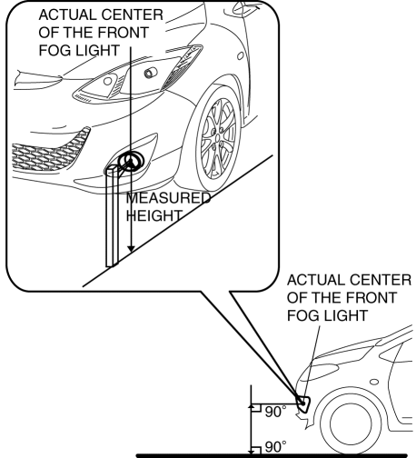
NOTE:
- Since the height of the vehicle varies depending on the vehicle situation, measure the height of the center of the front fog light using the actual vehicle.
7. Align the center of the adjustment screen with the position indicated in the figure, then affix the screen to the wall.
8. Place an object in front of the fog light not being adjusted to block its light beam.
9. Start the engine so that the battery remains charged.
10. Turn the front fog lights on.
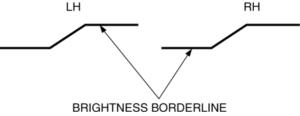
11. Verify that brightness border line of the front fog light is at the position indicated on the adjustment screen.
- If the brightness border line is not at the position indicated on the adjustment screen, perform the following adjustment.
12. Remove the screws shown in the figure and bend back the mudguard.
13. Loosen the adjustment bolt.
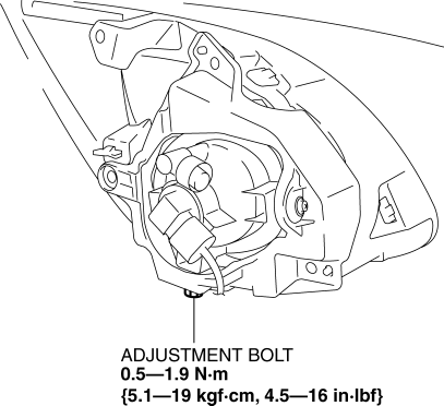
14. Move the front fog light in the direction of the arrow shown in the figure to adjust the brightness border line to the position indicated on the adjustment screen.
15. Tighten the adjustment bolt.
16. Install the screws and mudguard.
SIDE TURN LIGHT REMOVAL/INSTALLATION
1. Disconnect the negative battery cable.
2. Move the side turn light in the direction of the arrow (1) (toward the vehicle rear) and detach the tab.
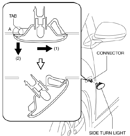
3. Pull area A of the side turn light in the direction of the arrow (2) and remove the side turn light.
4. Disconnect the connector.
5. Install in the reverse order of removal.
CAUTION:
- Always assemble the side turn light with the tab towards the vehicle rear.
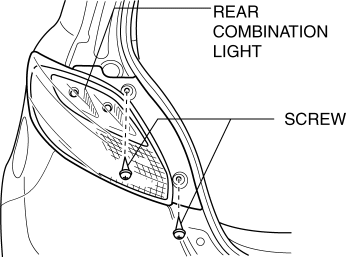
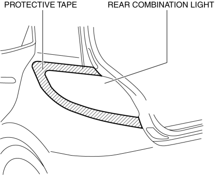
REAR COMBINATION LIGHT REMOVAL/INSTALLATION
1. Disconnect the negative battery cable.
2. Remove the screws.
3. To prevent scratches or damage, affix protective tape to the position shown in the figure.
NOTE:
- When the rear combination light is removed from the body, perform the procedure after affixing protective tape to the body. Otherwise, the body could interfere with the rear combination light and cause scratching or damage to the body.
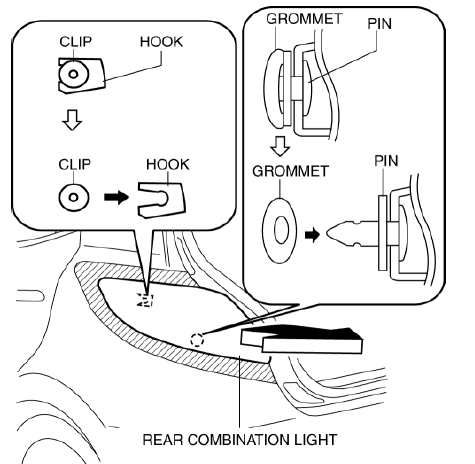
4. Pull the rear combination light in the direction of the arrow shown in the figure, remove the hook from the clip, and remove the pin from the grommet.
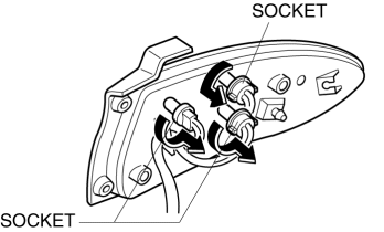
5. Rotate the socket in the direction of the arrow shown in the figure and remove it.
6. Remove the wiring harness from the hook.
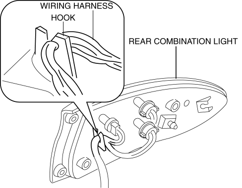
7. Remove the rear combination light.
8. Install in the reverse order of removal.
REAR COMBINATION LIGHT BULB REMOVAL/INSTALLATION
1. Disconnect the negative battery cable.
2. Remove the rear combination light. (See REAR COMBINATION LIGHT REMOVAL/INSTALLATION).
3. Remove the rear combination light bulbs.
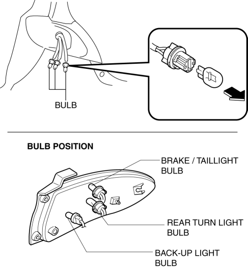
4. Install in the reverse order of removal.
HIGH MOUNT BRAKE LIGHT REMOVAL/INSTALLATION
1. Disconnect the negative battery cable.
2. Remove the liftgate upper trim. (See LIFTGATE UPPER TRIM REMOVAL/INSTALLATION).
3. Remove tabs A (4 locations).
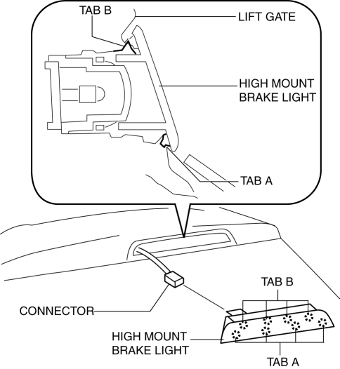
4. Remove the high-mount brake light while removing tabs B (4 locations).
5. Disconnect the connector.
6. Install in the reverse order of removal.
LICENSE PLATE LIGHT REMOVAL/INSTALLATION
1. Disconnect the negative battery cable.
2. Pull the tabs shown in the figure in the direction of the arrow (1) and remove them in the direction of the arrow (2).
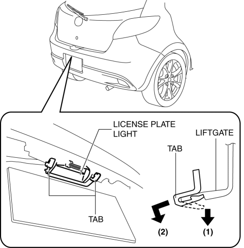
3. Pull out the wiring harness from the hook.
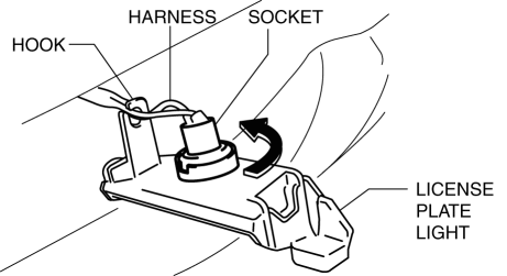
4. Rotate the socket in the direction of the arrow as shown in the figure to remove it.
5. Remove the license plate light.
6. Install in the reverse order of removal.
LICENSE PLATE LIGHT BULB REMOVAL/INSTALLATION
1. Disconnect the negative battery cable.
2. Insert a tape-wrapped flathead screwdriver into the service hole, push it in the direction of the arrow, and remove the lens.
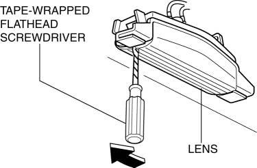
3. Remove the license plate light bulb.
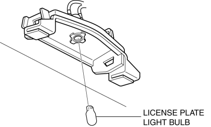
4. Install in the reverse order of removal.
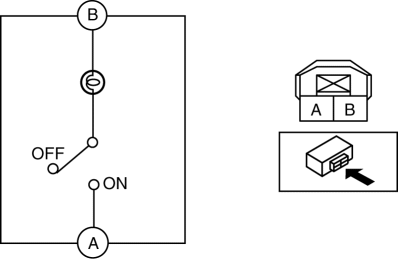
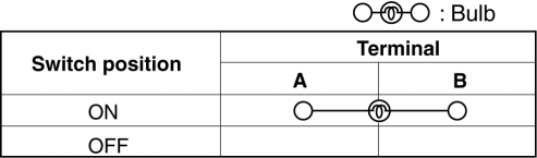
BACK-UP LIGHT SWITCH INSPECTION
1. Disconnect the negative battery cable.
2. Disconnect the back-up light switch connector. (See BACK-UP LIGHT SWITCH INSPECTION).
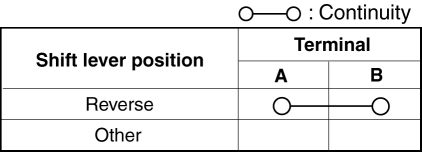
3. Verify that the continuity between the back-up light switch terminals is as indicated in the table.
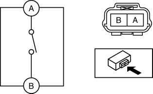
- If not as indicated in the table, replace the back-up light switch.
COMBINATION SWITCH REMOVAL/INSTALLATION
1. Disconnect the negative battery cable and wait 1 min or more.
2. Remove the following parts:
- Driver-side air bag module (See DRIVER-SIDE AIR BAG MODULE REMOVAL/INSTALLATION).
- Steering wheel (See STEERING WHEEL AND COLUMN REMOVAL/INSTALLATION).
- Column cover (See COLUMN COVER REMOVAL/INSTALLATION).
- Clock spring (See CLOCK SPRING REMOVAL/INSTALLATION).
3. Disconnect the connector.
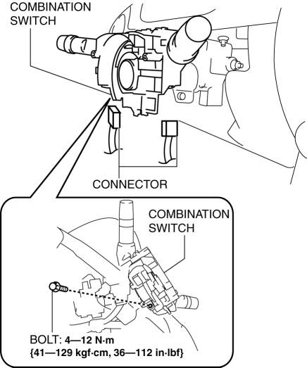
4. Remove the bolt.
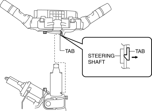
5. Detach the tab.
6. Remove the combination switch.
7. Install in the reverse order of removal.
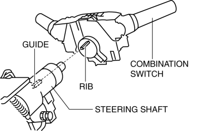
Combination Switch Installation Note
1. Align the combination switch rib with the steering shaft guide and press the combination switch until it contacts.
COMBINATION SWITCH DISASSEMBLY/ASSEMBLY
1. Disconnect the negative battery cable and wait 1 min or more.
2. Remove the following parts:
- Driver-side air bag module (See DRIVER-SIDE AIR BAG MODULE REMOVAL/INSTALLATION).
- Steering wheel (See STEERING WHEEL AND COLUMN REMOVAL/INSTALLATION).
- Column cover (See COLUMN COVER REMOVAL/INSTALLATION).
- Clock spring (See CLOCK SPRING REMOVAL/INSTALLATION).
3. Remove the combination switch. (See COMBINATION SWITCH REMOVAL/INSTALLATION).
4. Press the tabs in the direction of the arrow (1) shown in the figure, then remove the light switch, and the wiper and washer switch.
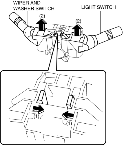
5. Assemble in the reverse order of disassembly.
LIGHT SWITCH REMOVAL/INSTALLATION
1. Disconnect the negative battery cable.
2. Remove the column cover. (See COLUMN COVER REMOVAL/INSTALLATION).
3. Disconnect the connector.
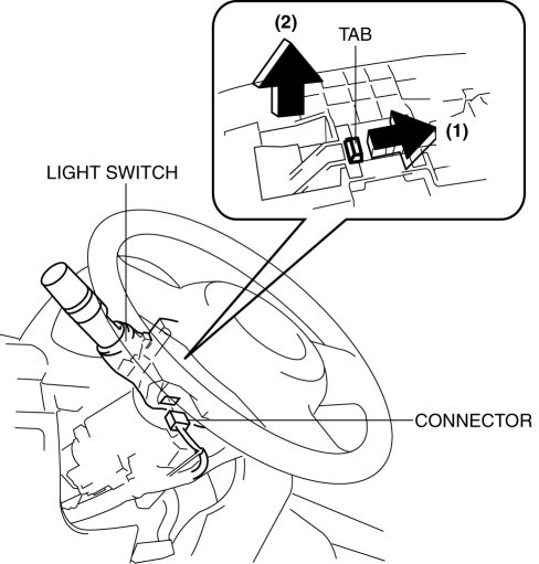
4. Release the tab in the direction of the arrow (1) shown in the figure and remove the light switch in the direction of the arrow (2).
5. Install in the reverse order of removal.
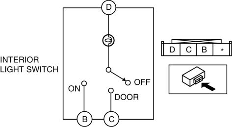
LIGHT SWITCH INSPECTION
1. Disconnect the negative battery cable.
2. Remove the column cover. (See COLUMN COVER REMOVAL/INSTALLATION).
3. Remove the light switch. (See LIGHT SWITCH REMOVAL/INSTALLATION).
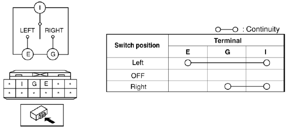
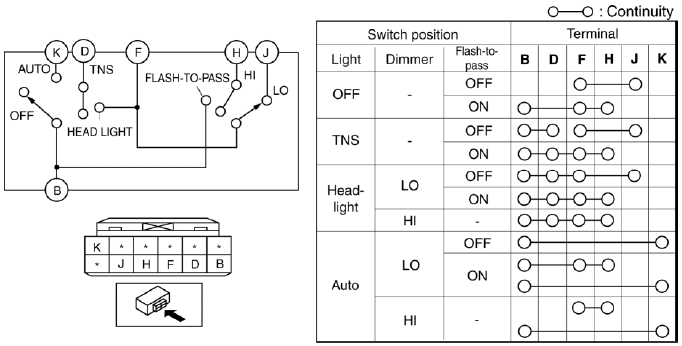
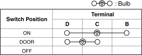
4. Verify that the continuity between the light switch terminals is as indicated in the table.
- If not as indicated in the table, replace the light switch.
Vehicles Without Auto Light System
Light switch
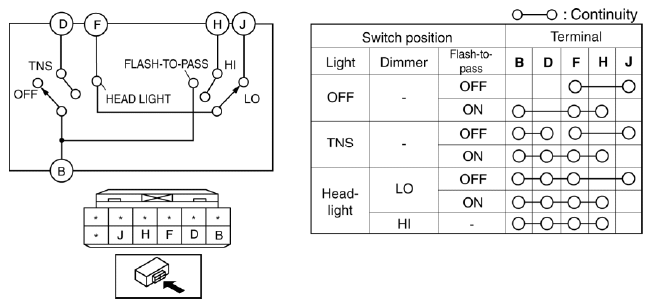
Turn switch
Vehicles With Auto Light System
Light switch
Turn switch
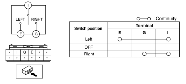
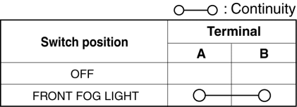
FRONT FOG LIGHT SWITCH INSPECTION
1. Disconnect the negative battery cable.
2. Remove the column cover. (See COLUMN COVER REMOVAL/INSTALLATION).
3. Remove the light switch. (See LIGHT SWITCH REMOVAL/INSTALLATION).
4. Verify that the continuity between the front fog light switch terminals is as indicated in the table using a circuit tester.
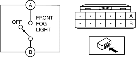
- If not as indicated in the table, replace the light switch.
HAZARD WARNING SWITCH REMOVAL/INSTALLATION
1. Disconnect the negative battery cable.
2. Remove the following parts:
- Front scuff plate (See FRONT SCUFF PLATE REMOVAL/INSTALLATION).
- Front side trim (See FRONT SIDE TRIM REMOVAL/INSTALLATION).
- Rear console (See REAR CONSOLE REMOVAL/INSTALLATION).
- Side wall (See SIDE WALL REMOVAL/INSTALLATION).
- Shift lever knob (MTX) (See MANUAL TRANSAXLE SHIFT MECHANISM REMOVAL/INSTALLATION).
- Front console component (See FRONT CONSOLE COMPONENT REMOVAL/INSTALLATION).
- Glove compartment (See GLOVE COMPARTMENT REMOVAL/INSTALLATION).
- Lower panel (See LOWER PANEL REMOVAL/INSTALLATION).
- Center panel unit (See CENTER PANEL UNIT REMOVAL/INSTALLATION).
3. Remove the hazard warning switch in the direction of the arrow (2) shown in the figure while pressing the tabs in the direction of the arrow (1).
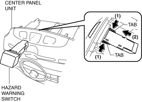
4. Install in the reverse order of removal.
HAZARD WARNING SWITCH INSPECTION
1. Disconnect the negative battery cable.
2. Remove the following parts:
- Front scuff plate (See FRONT SCUFF PLATE REMOVAL/INSTALLATION).
- Front side trim (See FRONT SIDE TRIM REMOVAL/INSTALLATION).
- Rear console (See REAR CONSOLE REMOVAL/INSTALLATION).
- Side wall (See SIDE WALL REMOVAL/INSTALLATION).
- Shift lever knob (MTX) (See MANUAL TRANSAXLE SHIFT MECHANISM REMOVAL/INSTALLATION).
- Front console component (See FRONT CONSOLE COMPONENT REMOVAL/INSTALLATION).
- Glove compartment (See GLOVE COMPARTMENT REMOVAL/INSTALLATION).
- Lower panel (See LOWER PANEL REMOVAL/INSTALLATION).
- Center panel unit (See CENTER PANEL UNIT REMOVAL/INSTALLATION).
- Hazard warning switch (See HAZARD WARNING SWITCH REMOVAL/INSTALLATION).
3. Verify that the continuity between the hazard warning switch terminals is as indicated in the table.
- If not as indicated in the table, replace the hazard warning switch.
INTERIOR LIGHT REMOVAL/INSTALLATION
1. Disconnect the negative battery cable.
2. Remove the following parts:
- A-pillar trim (See A-PILLAR TRIM REMOVAL/INSTALLATION).
- Sunvisor (See SUNVISOR REMOVAL/INSTALLATION).
- Assist handle (See ASSIST HANDLE REMOVAL/INSTALLATION).
- Rain sensor cover (vehicles with auto light/wiper system ) (See RAIN SENSOR REMOVAL/INSTALLATION).
3. Set the headliner out of the way.
4. Release the tabs in the direction of the arrow (1) shown in the figure and remove the interior light in the direction of the arrow (2).
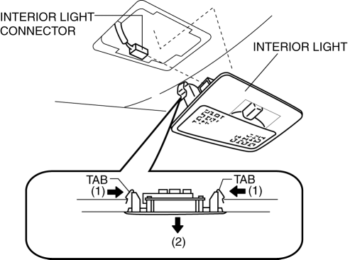
5. Disconnect the interior light connector.
6. Install in the reverse order of removal.
INTERIOR LIGHT BULB REMOVAL/INSTALLATION
1. Disconnect the negative battery cable.
2. Insert a tape-wrapped flathead screwdriver into the service hole, push it in the direction indicated by the arrow, and remove the lens.
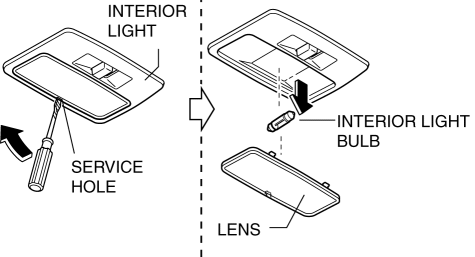
3. Remove the interior light bulb.
4. Install in the reverse order of removal.
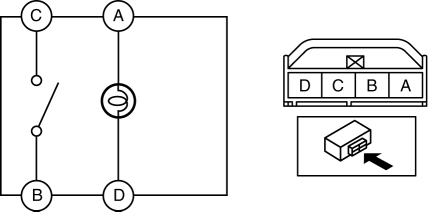
INTERIOR LIGHT INSPECTION
1. Remove the following parts:
- A-pillar trim (See A-PILLAR TRIM REMOVAL/INSTALLATION).
- Sunvisor (See SUNVISOR REMOVAL/INSTALLATION).
- Assist handle (See ASSIST HANDLE REMOVAL/INSTALLATION).
- Rain sensor cover (vehicles with auto light/wiper system) (See RAIN SENSOR REMOVAL/INSTALLATION).
- Interior light (See INTERIOR LIGHT REMOVAL/INSTALLATION).
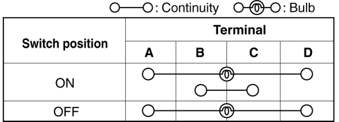
2. Verify that the continuity between the interior light terminals is as indicated in the table.
- If not as indicated in the table, replace the interior light.
CARGO COMPARTMENT LIGHT REMOVAL/INSTALLATION
1. Disconnect the negative battery cable.
2. Insert hand through the service hole, release the tab in the direction of the arrow (1) shown in the figure, and pull area A in the direction of the arrow (2) to remove the cargo compartment light.
3. Disconnect the cargo compartment light connector.
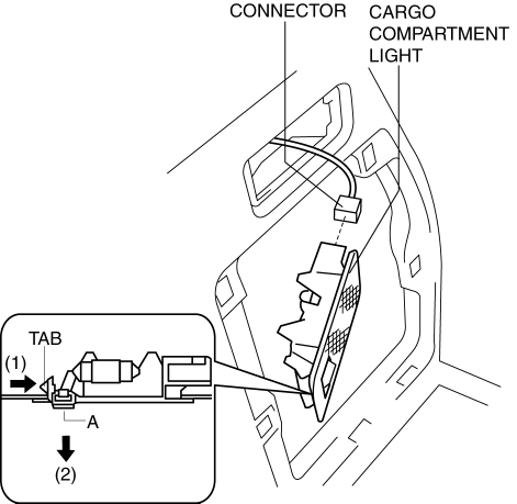
4. Install in the reverse order of removal.
CARGO COMPARTMENT LIGHT BULB REMOVAL/INSTALLATION
1. Disconnect the negative battery cable.
2. Remove the cargo compartment light. (See CARGO COMPARTMENT LIGHT REMOVAL/INSTALLATION).
3. Remove the cargo compartment light bulb.
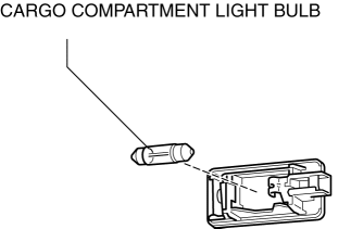
4. Install in the reverse order of removal.
CARGO COMPARTMENT LIGHT INSPECTION
1. Disconnect the negative battery cable.
2. Remove the cargo compartment light. (See CARGO COMPARTMENT LIGHT REMOVAL/INSTALLATION).
3. Verify that the continuity between the cargo compartment light terminals is as indicated in the table.
- If not as indicated in the table, replace the cargo compartment light.
LIGHTING SYSTEM PERSONALIZATION FEATURES SETTING PROCEDURE
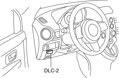
1. Connect the M-MDS(IDS) to the DLC-2.
2. After vehicle identification, the following can be selected from the M-MDS initialization screen.
- Select the "Module Programming"
3. Then, select items from the screen menu in the following order.
- Select "Programmable Parameters"
- Select "BCM/GEM"
4. Select an item name, and then select option.
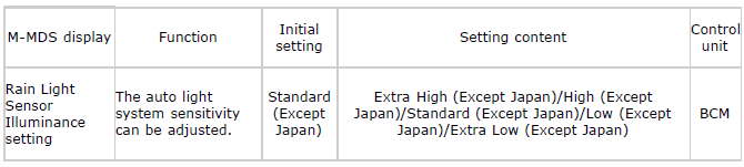
NOTE:
- Other than the above conditions, a "Japan Only" contents is also displayed, however, do not select the contents because it is for use in Japan Only.
- If the mode is set to "Extra High (Except Japan)" and "High (Except Japan)", the illumination level for illuminating the TNS and headlight increases. Therefore, the TNS and headlights illuminate when the ambient light is brighter than when the level is set to "Standard (Except Japan)". In addition, if the mode is set to "Low (Except Japan)" and "Extra Low (Except Japan)", the illumination level for illuminating the TNS and headlights decreases. Therefore, the TNS and headlights illuminate when the ambient light is lower than when the level is set to "Standard (Except Japan)".

